00192328-01.pdf - 第67页
SIPLACE S-25 HM 2 Retrofitt. Instruct. RV6-DLM1 Head & Nozzle Chang. RV6 Standa rd (Optionen) 02/01 Issue 2.4 Sequence: Ins talling the Hardware 65 ,QVW DOOLQJW KH1HZ1R]]O H&KDQJHU59 6W DQGDUG .H\…
2 Retrofitt. Instruct. RV6-DLM1 Head & Nozzle Chang. RV6 Standard (Optionen) SIPLACE S-25 HM
2.4 Sequence: Installing the Hardware 02/01 Issue
64
'HLQVWDOOLQJWKH1R]]OH&KDQJHU596WDQGDUG
DANGER
Obey all safety instructions in Section 2.2.
The machine must be turned OFF and isolated from the mains, especially for all work in the vicinity
of the cutter. In addition, the compressed air feeder at the main valve of the compressed air unit
in the machine frame must be turned OFF and the compressed air lines bled by actuating the nee-
dle valve on the compressed air unit.
Never reach into the cutter from above or below. Even when the machine is OFF, you can still in-
jury yourself on the blades of the cutter.
Secure the machine conscientiously as described in the chapter "Locking the Machine..." in the
User Manual to prevent it from being turned back ON without authorization.
WARNING
While retrofitting, also make certain that the DANGER symbol and the DANGER text are placed
on the cover of the cutter (see: Section 2.3).
CAUTION
Make certain that now screws or other hardware fall into the cutter during the following de-instal-
lation / installation work.
Å On the bottom of the nozzle changer, loosen the electrical and pneumatic connections (see:
Fig. 2.4.8), incl. cable tie on the nozzle changer (see: Fig. 2.4.9).
Å Remove the 12-segment nozzle changer (RV12 Standard):
Undo the 2 socket hex head cap screws M4 above the spacer bolts (as shown in Fig. 2.4.8).
Lift out the nozzle changer.
SIPLACE S-25 HM 2 Retrofitt. Instruct. RV6-DLM1 Head & Nozzle Chang. RV6 Standard (Optionen)
02/01 Issue 2.4 Sequence: Installing the Hardware
65
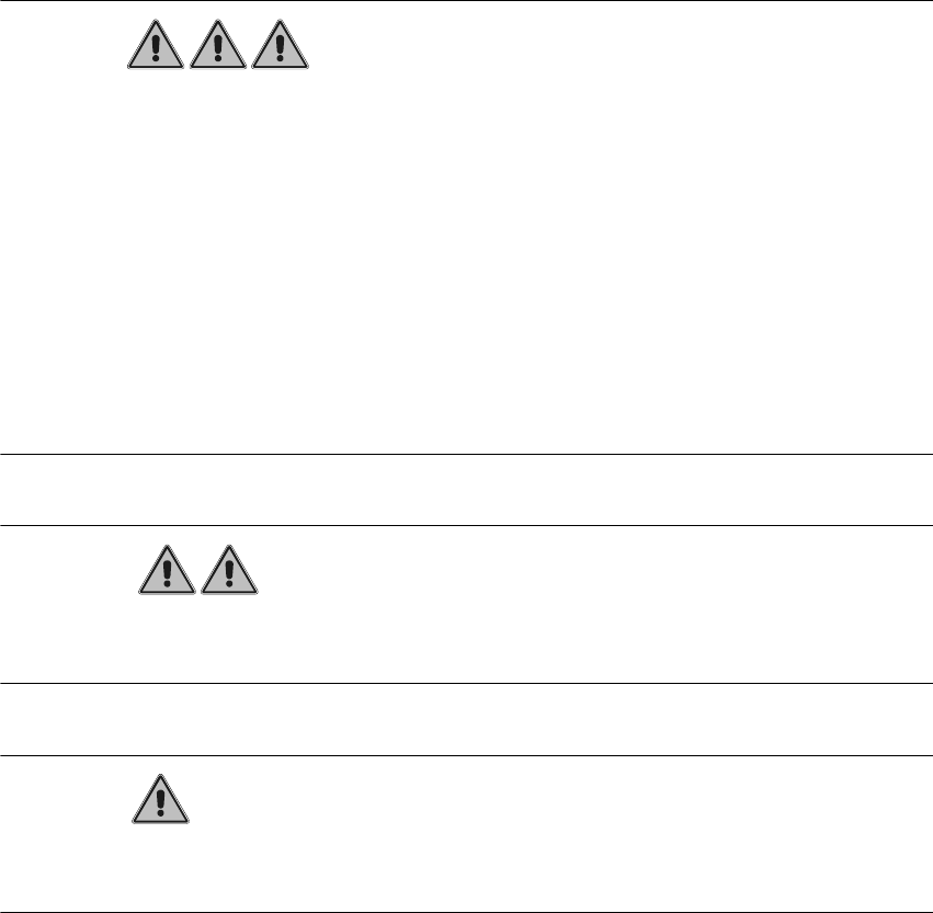
,QVWDOOLQJWKH1HZ1R]]OH&KDQJHU596WDQGDUG
.H\
1. Fastening screws for nozzle changer: 4 socket hex head cap screws M4
2. Electrical and compressed air connections on bottom of the nozzle changer
3. Nozzle changer for 12-segment revolver head, modular
4. Empty-tape duct (is not dismantled)
5. Carrier for empty-tape duct and nozzle changer, Item no. 00350480-01 (is not dismantled)
6. Bar with 2 fiducials (from retrofit kit), for nozzle changer; required for software version 502.01
2 Retrofitt. Instruct. RV6-DLM1 Head & Nozzle Chang. RV6 Standard (Optionen) SIPLACE S-25 HM
2.4 Sequence: Installing the Hardware 02/01 Issue
66
Å Use the nozzle changer RV6 Standard from the retrofit kit (see Section 2.3.2).
Å Make the electrical and pneumatic connection on the bottom of the new nozzle changer as
shown below.
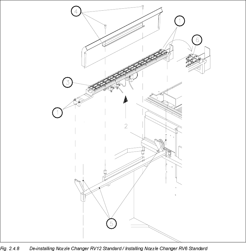
Å Fasten the interface cable of the nozzle changer and the compressed air hose to the back of
the new nozzle changer with a cable tie as shown above.
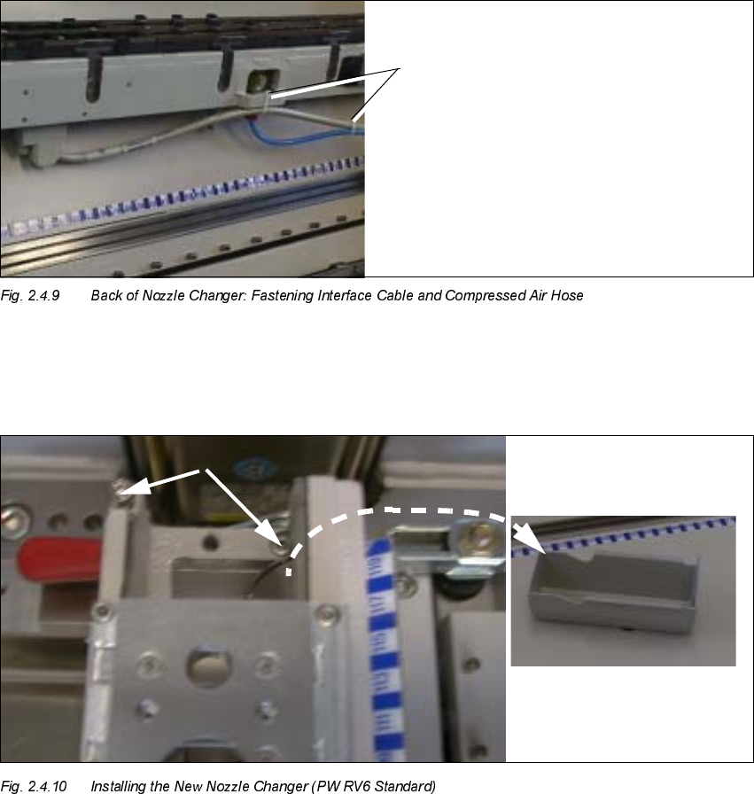
Å Place the new nozzle changer correctly into the fixed location pins of the carrier.
.H\
1. Reject box, removed
2. Screws fastening the nozzle changer RV6 Standard, RH side
Cable ties