00192328-01.pdf - 第76页
2 Retrofitt. Instruct. RV6-DLM1 Head & Nozzle Chang. RV6 Standard (Optionen) S IPLACE S-25 HM 2.5 SITEST: Adjust Configuration, Entry Zero Point Compens. Values RV6 Head 02/01 Issue 74 (QWU \=HUR3RLQW&R…
SIPLACE S-25 HM 2 Retrofitt. Instruct. RV6-DLM1 Head & Nozzle Chang. RV6 Standard (Optionen)
02/01 Issue 2.5 SITEST: Adjust Configuration, Entry Zero Point Compens. Values RV6 Head
73
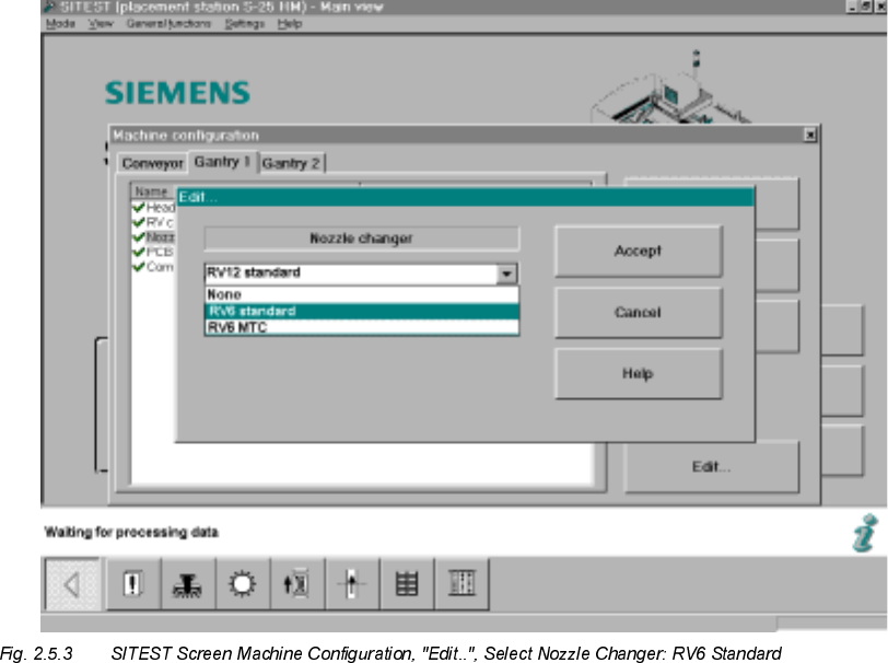
Å Click on "RV6 Standard" (long nozzle changer for the RV6 head) -> Select "Accept" (button).
Take note of:
If a RV6-DLM1 head AND an MTC was retrofitted, select the nozzle changer "RV6 MTC" ->
"Accept" (button) -> again "Accept".
After the overall reference run, the nozzle changer MTC is configured and measured in accor-
dance with the Retrofitting Instructions for MTC, Item no. see: Section 2.3.6.
Å Calibrate the nozzle changer after the dynamics adjustment and the calibration of the heads,
i.e., after taking the steps below (see: Section 2.8).
&RQFOXGLQJ$FFHSWDQFHRIWKH&RQILJXUDWLRQ
Å After completely adjusting the machine configuration:
Exit the menu "Machine Configuration" by pressing "Accept" (button).
The main view will be displayed and the messsage will appear:
7KHPDFKLQHFRQILJXUDWLRQKDVFKDQJHG
6KXWGRZQ!5HVWDUWPDFKLQH!&OLFNRQ2.EXWWRQ
Å Boot up the machine and change back to the SITEST program.
2 Retrofitt. Instruct. RV6-DLM1 Head & Nozzle Chang. RV6 Standard (Optionen) SIPLACE S-25 HM
2.5 SITEST: Adjust Configuration, Entry Zero Point Compens. Values RV6 Head 02/01 Issue
74
(QWU\=HUR3RLQW&RPSHQVDWLRQ9DOXHVRIWKH1HZ3ODFHPHQW+HDG
Å $)7(5WKHUHVWDUWWUDQVIHUWKH]HURSRLQWFRPSHQVDWLRQYDOXHVRQWKHODEHORIWKHSODFH
PHQWKHDGMXVWLQVWDOOHGYLVLEOHLQDVVHPEOHGFRQGLWLRQ
Å For the entry, select the menu +HDGH[FKDQJHin the SITEST main view or select:
-> ICON "Axis functions of the revolver head" -> Activate the relevant axis (z-, star, dp) by
clicking on the radio button -> Click on "Positions" (button).
Å Select "Zero point compensation" -> Edit -> Transfer the value from the label -> Click on
"Accept" (button)
Å Carry out the transfer of the remaining zero point compensations from the label in the same
manner.
Å 1RZFDUU\RXWWKHRYHUDOOUHIHUHQFHUXQEXWWRQ

SIPLACE S-25 HM 2 Retrofitt. Instruct. RV6-DLM1 Head & Nozzle Chang. RV6 Standard (Optionen)
02/01 Issue 2.6 Setting the Dynamics
75
6HWWLQJWKH'\QDPLFV
CAUTION
After exchanging a placement head the setting of the dynamics must always be checked.
When changing from the 12- to the 6-segment head (optional) in particular, the Z-axis is much too
fast and the P-component much too low.
It is IMPERATIVE that the dynamics be set.
In addition, when the modular head board (optional) is installed, the track signals must also be
calibrated.
Å For the new 6-segment revolver head, modular, calibrate the Z-axis and the dp-axis.
To do so, proceed according to the setting instructions in SITEST -> +HOS -> Setting of
dynamics or according to the Setting Instructions (Item no. see: Section 2.3.6).
&DOLEUDWLQJWKH3ODFHPHQW+HDGVDQG&DPHUDV
5HTXLUHPHQWV
– The dynamics must be set.
– To use the final operating conditions as a basis, we recommend that the protective covers of
both placement heads be mounted first.
NOTE:
If errors occur during the calibration, you may be using the incorrect axis data.
Consequence: During calibration, the part to be calibrated is only turned 45° or the machine’s zero
point is incorrect (by 5 mm or a multiple thereof).
If an error occurs, change the configuration back to the 12-segment head and then back to the
6-nozzle head.
Å Calibrate the "Placement heads and cameras" as described in the Software Guide
SITEST V 502.xx.
This calibration is a prerequisite for measuring the nozzle changer.