00192328-01.pdf - 第82页
2 Retrofitt. Instruct. RV6-DLM1 Head & Nozzle Chang. RV6 Standard (Optionen) S IPLACE S-25 HM 2.8 SITEST: Loading Noz zle Changer RV 6 Standard w ith Nozzles and Calibrating 02/01 Issue 80 &DOLEUDWL Q J1R]…
SIPLACE S-25 HM 2 Retrofitt. Instruct. RV6-DLM1 Head & Nozzle Chang. RV6 Standard (Optionen)
02/01 Issue 2.8 SITEST: Loading Nozzle Changer RV6 Standard with Nozzles and Calibrating
79
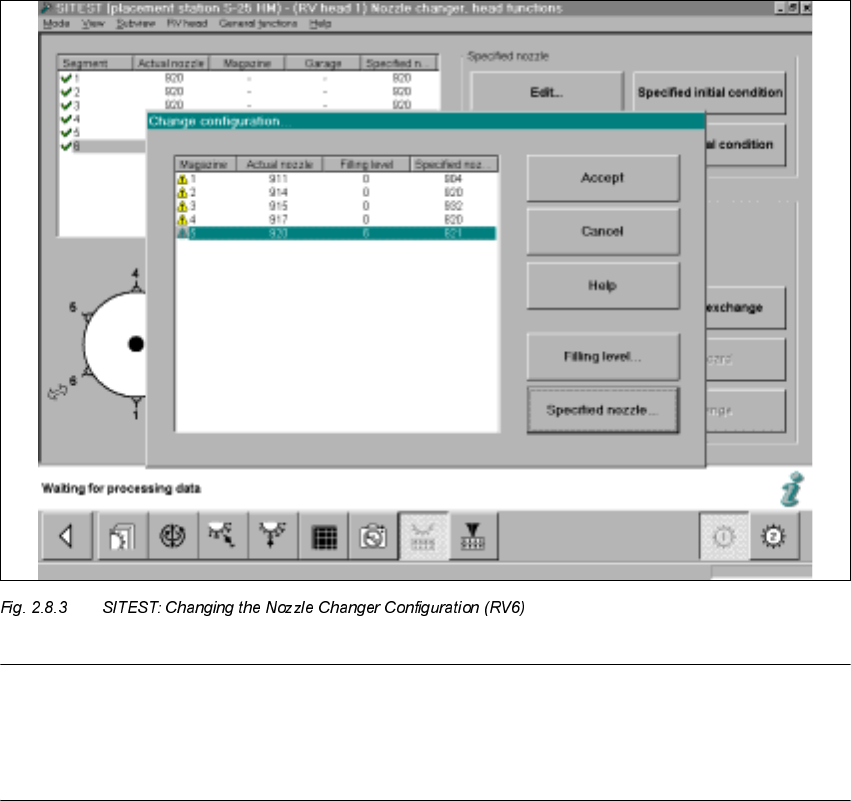
Å Select "Nozzle changer, head functions -> "Change configuration".
The following screen will appear:
NOTE:
The RV6 nozzle changer must be configured complete with nozzles.
- 900-series magazines must be defined with 900-series nozzle type (e.g., type 920),
- 800-series magazines with an 800-series nozzle type (e.g., type 820).
Å For each magazine, select the SPECIFIED nozzle (e.g., type 920 / 820) that was previously
defined on the head -> Select "Accept" (button) to accept this nozzle as the ACTUAL nozzle.
Å For each magazine, set the "Filling level" (button) to "0" -> Select "Accept" (button) -> Check
the filling levels.
Å If a RV6 head has already been installed on gantry 2, conduct the configuration process de-
scribed for gantry 2 (not necessary in the case of the 12-segment revolver head).
2 Retrofitt. Instruct. RV6-DLM1 Head & Nozzle Chang. RV6 Standard (Optionen) SIPLACE S-25 HM
2.8 SITEST: Loading Nozzle Changer RV6 Standard with Nozzles and Calibrating 02/01 Issue
80
&DOLEUDWLQJ1R]]OH&KDQJHU596WDQGDUG
5HTXLUHPHQW
Loaded with nozzles as described in Section 2.8.1.
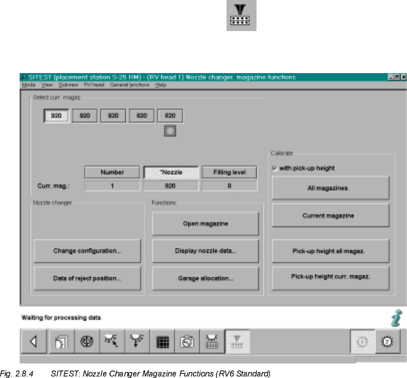
Å To measure / calibrate the new nozzle changer, select
the ICON "Nozzle changer magazine functions" .
The following screeen for nozzle changer RV6 Standard will be displayed:
Å If necessary, check the magazine configuration with nozzles and the filling level "0" (buttons)
again -> see: Fig. 2.8.4.
Å In the field "Calibration", activate the function "ZLWKpickup height -> Select "All magazines"
(button):-> see: Fig. 2.8.4:
Å The calibration of the nozzle changer RV6 Standard follows.
First, the fiducials of the magazines and then the fiducials of the reject box are measured ->
Then the pick-up heights of the individual magazines are ascertained.
SIPLACE S-25 HM 2 Retrofitt. Instruct. RV6-DLM1 Head & Nozzle Chang. RV6 Standard (Optionen)
02/01 Issue 2.8 SITEST: Loading Nozzle Changer RV6 Standard with Nozzles and Calibrating
81
Å In conclusion, check the pick-up heights ascertained for EACH magazine individually:
Select the magazines in succession by clicking on the relevant button -> Select "Display nozzle
data" each time.
Å For EACH magazine individually, check the ascertained values in the ODVWFROXPQ
– The max. permissible tolerance of all of the values of each magazine UHODWLYHWRHDFK
QHLJKERULQJPDJD]LQHis +/-10 digits.
– The values of the last column of a magazine must be in the range between 870 to 929 digits.
Å If the values are okay, select "Settings" -> Store machine data".
Å If there are deviations, check the following:
Å Is the mounting surface of the nozzle changer holder satisfactory/clean?
Å Was the nozzle changed correctly? Does the nozzle move sluggishly on the sleeve?
Å After eliminating the cause of the problem, repeat the determination of the pick-up heights,
including checking and storing the values, as described above.
Å Close the SITEST program and restart the machine.
Å Continue the work with "RV mapping".
590DSSLQJ
Å Carry out the"RV mapping" for the RV6-DLM1 head / for the pertinant gantry, as described in
the Software Guide SITEST V 502.xx.
3UHFLVLRQ&DOLEUDWLRQ
Å
Carry out the precision calibration as described in the Software Guide SITEST V 502.xx.
/LQH&RPSXWHU&RQILJXUDWLRQRI59+HDG1R]]OH&KDQJHU59
Å Configure the new placement head RV6 and the nozzle changer RV6 Standard (or MTC) in the
Station editor, as described in the Description of Software Version LRU 502.xx.