GWS 6-100 S角磨机说明书.pdf - 第11页
English | 11 Bosch Power Tools 1 609 92A 2V9 | (23.11.16) Rubber Sanding Plate For operations with the rubber sanding plate 1 8, al- ways mount the hand guard 17. See graphics page fo r the mounting sequence. Screw on …
10 | English
1 609 92A 2V9 | (23.11.16) Bosch Power Tools
Assembly
Mounting the Protective Devices
Before any work on the machine itself, pull the mains
plug.
Note: After breakage of the grinding disc during operation or
damage to the holding fixtures on the protection guard/power
tool, the machine must promptly be sent to an after-sales
service agent for maintenance. For addresses, see section
“After-sales Service and Application Service”.
Protection Guard for Grinding
Place the protection guard 8 on the spindle collar. Adapt the
position of the protection guard 8 to the requirements of the
work step. Lock protection guard 8 by tightening locking
screw 9 with combination spanner 5/6.
Adjust the protection guard 8 in such a manner that
sparking is prevented in the direction of the operator.
Note: The encoding keys on the protection guard 8 ensure
that only a protection guard that fits the machine type can be
mounted.
Protection Guard for Cutting
For cutting with bonded abrasives, always use the pro-
tection guard for cutting 15.
Provide for sufficient dust extraction when cutting
stone.
The protection guard for cutting 15 is mounted in the same
manner as the protection guard for grinding 8.
Cutting Guide with Dust Extraction Protection Guard
The cutting guide with dust extraction protection guard 22 is
mounted in the same manner as the protection guard for
grinding 8.
Auxiliary Handle
Operate your machine only with the auxiliary handle 4.
Screw the auxiliary handle 4 on the right or left of the machine
head depending on the working method.
Hand Guard
For operations with the rubber sanding plate 18 or with
the cup brush/wheel brush/flap disc, always mount the
hand guard 17.
The hand guard 17 is fastened with the auxiliary handle 4.
Mounting the Grinding Tools
Before any work on the machine itself, pull the mains
plug.
Do not touch grinding and cutting discs before they
have cooled down. The discs can become very hot while
working.
Clean the grinder spindle 7 and all parts to be mounted.
For clamping and loosening the grinding tools, lock the grind-
er spindle with the spindle lock button 1.
Actuate the spindle lock button only when the grinder
spindle is at a standstill. Otherwise, the machine may be-
come damaged.
Grinding/Cutting Disc
Pay attention to the dimensions of the grinding tools. The
mounting hole diameter must fit the mounting flange without
play. Do not use reducers or adapters.
When using diamond cutting discs, pay attention that the di-
rection-of-rotation arrow on the diamond cutting disc and the
direction of rotation of the machine (see direction-of-rotation
arrow on the machine head) agree.
See graphics page for the mounting sequence.
To fasten the grinding/cutting disc, screw on the clamping nut
12 and tighten it with the combination spanner 5/6, (see sec-
tion “Quick-clamping Nut”).
After mounting the grinding tool and before switching
on, check that the grinding tool is correctly mounted
and that it can turn freely. Make sure that the grinding
tool does not graze against the protection guard or oth-
er parts.
Mounting flange for grinding spindle
M 14: A plastic part (O-ring) is fitted
around the centring collar of mounting
flange 10. If the O-ring is missing or
damaged, the mounting flange 10
must be replaced before resuming op-
eration.
Mounting flange for grinding spindle
M 10: The mounting flange can be used
on both sides.
Flap Disc
For operations with the flap disc, always mount the
hand guard 17.
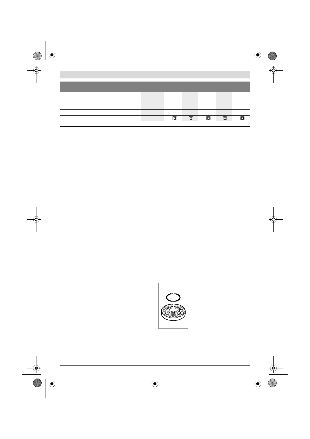
Thread of grinder spindle
M 10 M 14 M 14 M 14 M 14
Thread length (max.) of grinder spindle
mm 17 22 22 22 22
Speed preselection
– –
Weight according to EPTA-Procedure 01:2014
kg 1.8 1.9 1.9 1.9 1.9
Protection class
/II /II /II /II /II
Angle Grinder GWS...
Professional
6-100 E 6-115 6-115 E 6-125 6-125 E
The values given are valid for a nominal voltage [U] of 230 V. For different voltages and models for specific countries, these values can vary.
OBJ_BUCH-704-005.book Page 10 Wednesday, November 23, 2016 10:50 AM
English | 11
Bosch Power Tools 1 609 92A 2V9 | (23.11.16)
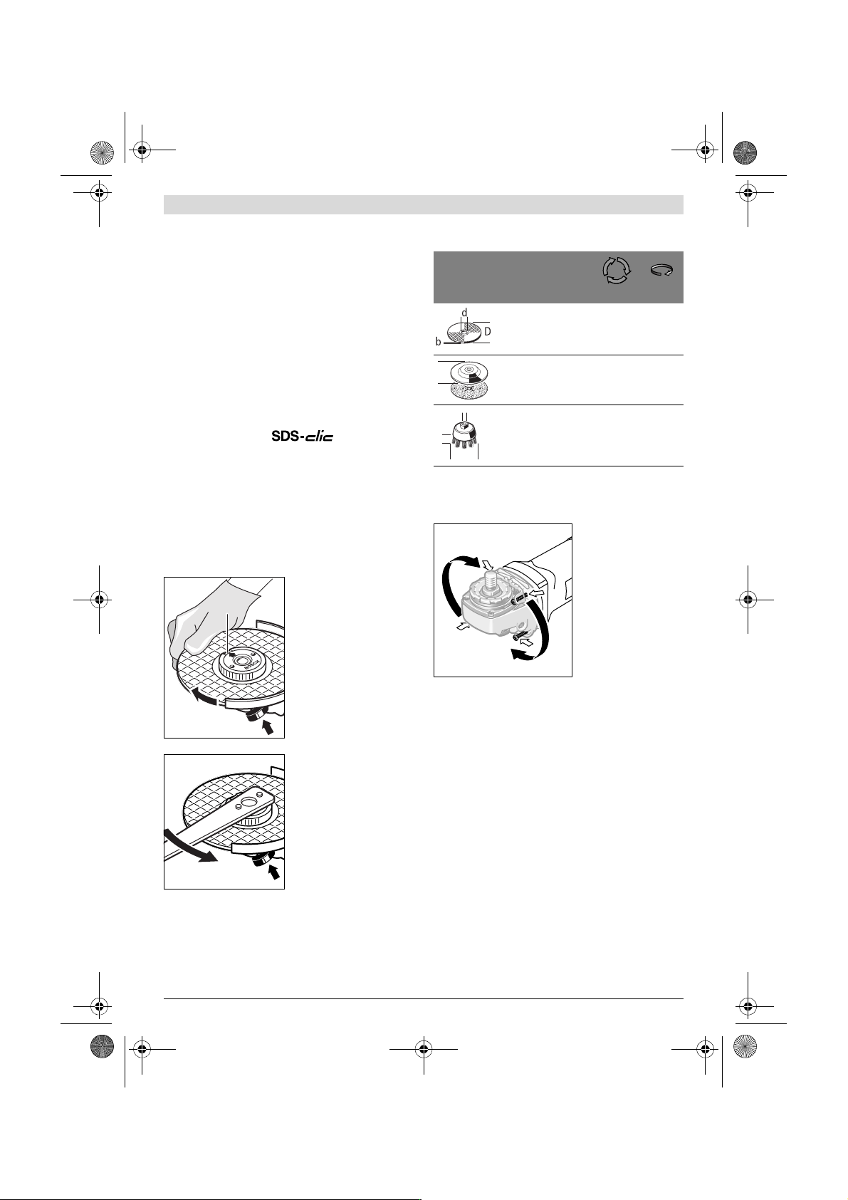
Rubber Sanding Plate
For operations with the rubber sanding plate 18, al-
ways mount the hand guard 17.
See graphics page for the mounting sequence.
Screw on round nut 20 and tighten it with the combination
spanner 5/6.
Cup Brush/Disc Brush
For operations with the cup brush/wheel brush, always
mount the hand guard 17.
See graphics page for the mounting sequence.
The cup brush/disc brush must be able to be screwed onto
the grinder spindle until it rests firmly against the grinder
spindle flange at the end of the grinder spindle threads. Tight-
en the cup brush/disc brush with an open-end spanner.
Quick-clamping Nut
For convenient changing of grinding tools without the use of
additional tools, you can use the quick-clamping nut 13 in-
stead of the clamping nut 12.
The quick-clamping nut 13 may be used only for grind-
ing or cutting discs.
Use only a flawless, undamaged quick-clamping nut 13.
When screwing on, pay attention that the side of the
quick-clamping nut 13 with printing does not face the
grinding disc; the arrow must point to the index mark 25.
Lock the grinder spindle with
the spindle lock button 1. To
tighten the quick-clamping
nut, firmly turn the grinding
disc in clockwise direction.
A properly fastened, undam-
aged quick-clamping nut can
be manually loosened by
turning the knurled ring in an-
ticlockwise direction.
Never loosen a tight quick-
clamping nut using pliers;
always use the combination
spanner. Apply the combina-
tion spanner 5/6 as shown in
the figure.
Approved Grinding Tools
All grinding tools mentioned in these operating instructions
can be used.
The permissible speed [min
-1
] or the circumferential speed
[m/s] of the grinding tools used must at least match the values
given in the table.
Therefore, observe the permissible rotational/circumferen-
tial speed on the label of the grinding tool.
Rotating the Machine Head
Before any work on the machine itself, pull the mains
plug.
The machine head can be
rotated with respect to
the machine housing in
90° steps. In this man-
ner, the On/Off switch
can be brought into a
more convenient posi-
tion for special working
situations, e.g. for left-
handed persons.
Completely unscrew the
four screws. Rotate the
machine head carefully,
without removing it from the housing, to the new position.
Screw in and tighten the four screws again.
Dust/Chip Extraction
Dust from materials such as lead-containing coatings,
some wood types, minerals and metal can be harmful to
one’s health. Touching or breathing-in the dust can cause
allergic reactions and/or lead to respiratory infections of
the user or bystanders.
Certain dust, such as oak or beech dust, is considered car-
cinogenic, especially in connection with wood-treatment
additives (chromate, wood preservative). Materials con-
taining asbestos may only be worked by specialists.
– As far as possible, use a dust extraction system suitable
for the material.
– Provide for good ventilation of the working place.
– It is recommended to wear a P2 filter-class respirator.
Observe the relevant regulations in your country for the
materials to be worked.
Prevent dust accumulation at the workplace. Dust can
easily ignite.
25
max.
[mm]
[mm]
D b d [min
-1
] [m/s]
100
115
125
6
6
6
16.0
22.2
22.2
11000
11000
11000
80
80
80
100
115
125
–
–
–
–
–
–
11000
11000
11000
80
80
80
70
75
30
30
M 10
M14
11000
11000
45
45
D
D
b
d
OBJ_BUCH-704-005.book Page 11 Wednesday, November 23, 2016 10:50 AM
12 | English
1 609 92A 2V9 | (23.11.16) Bosch Power Tools
Operation
Starting Operation
Observe correct mains voltage! The voltage of the pow-
er source must agree with the voltage specified on the
nameplate of the machine. Power tools marked with
230 V can also be operated with 220 V.
When operating the machine with power from mobile genera-
tors that do not have sufficient reserve capacity or are not
equipped with suitable voltage control with starting current
amplification, loss of performance or untypical behavior can
occur upon switching on.
Please observe the suitability of the power generator being used,
particularly with regard to the mains voltage and frequency.
Switching On and Off
To start the power tool, push the On/Off switch 2 forwards.
To lock the On/Off switch 2, press the On/Off switch 2 down
at the front until it latches.
To switch off the power tool, release the On/Off switch 2 or,
if it is locked, briefly push down the back of the On/Off switch
2 and then release it.
To save energy, only switch the power tool on when using it.
Check grinding tools before using. The grinding tool
must be mounted properly and be able to move freely.
Carry out a test run for at least one minute with no load.
Do not use damaged, out-of-centre or vibrating grind-
ing tools. Damaged grinding tools can burst and cause in-
juries.
Speed preselection (GWS 6-100 E/GWS 6-115 E/GWS 6-125 E)
The required speed can be preselected with the thumbwheel 3 (also while running).
The data in the following table are recommended values.
Working Advice
Exercise caution when cutting slots in structural walls;
see Section “Information on Structures”.
Clamp the workpiece if it does not remain stationary
due to its own weight.
Do not strain the machine so heavily that it comes to a
standstill.
After heavily straining the power tool, continue to run
it at no-load for several minutes to cool down the acces-
sory.
Do not touch grinding and cutting discs before they
have cooled down. The discs can become very hot while
working.
Do not use the power tool with a cut-off stand.
Rough Grinding
Never use a cutting disc for roughing.
The best roughing results are achieved when setting the ma-
chine at an angle of 30° to 40°. Move the machine back and
forth with moderate pressure. In this manner, the workpiece
will not become too hot, does not discolour and no grooves
are formed.
Flap Disc
With the flap disc (accessory), curved surfaces and profiles
can be worked.
Flap discs have a considerably higher service life, lower noise
levels and lower sanding temperatures than conventional
sanding sheets.
Cutting Metal
For cutting with bonded abrasives, always use the pro-
tection guard for cutting 15.
When cutting, work with moderate feed, adapted to the mate-
rial being cut. Do not exert pressure onto the cutting disc, tilt
or oscillate the machine.
Do not reduce the speed of running down cutting discs by ap-
plying sideward pressure.
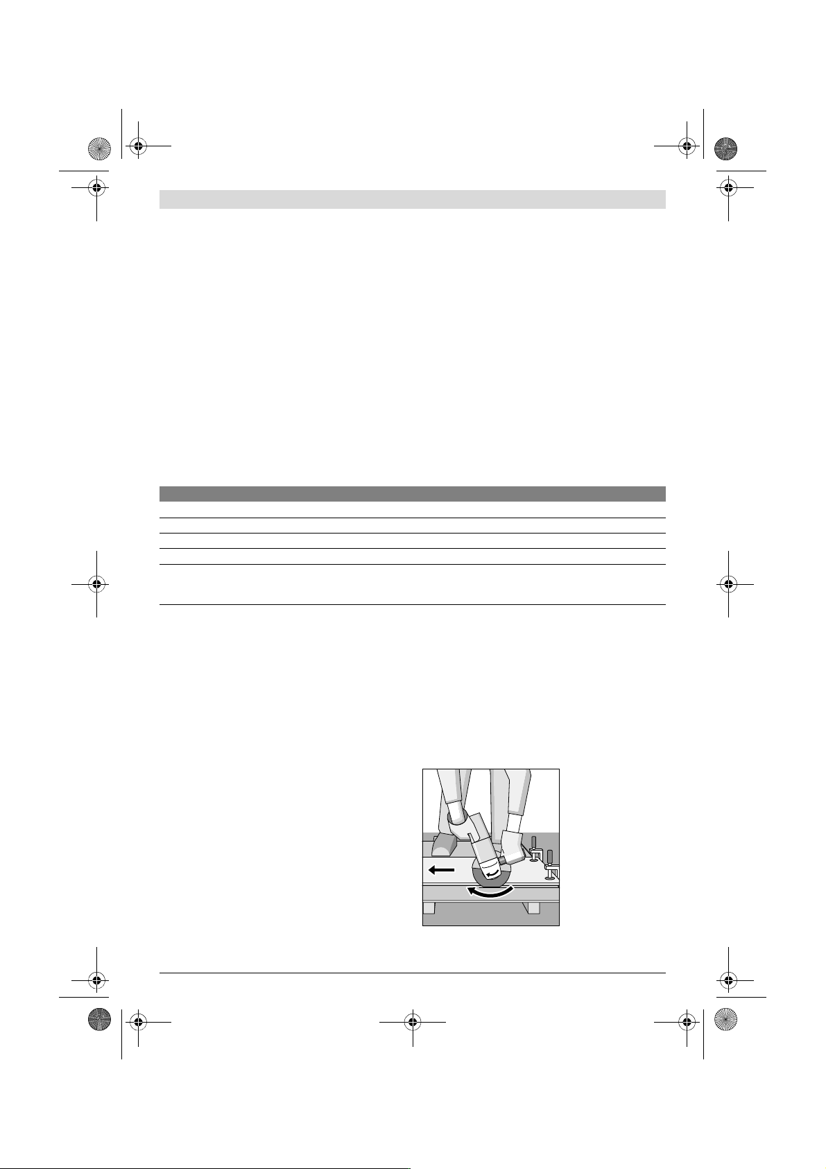
The machine must al-
ways work in an up-
grinding motion. Other-
wise, the danger exists
of it being pushed un-
controlled out of the
cut.
When cutting profiles and square bar, it is best to start at the
smallest cross section.
Material Application Accessory Thumbwheel Position
Metal Removing paint Sanding disc 2 – 3
Wood, metal Brushing, rust removal Cup brush, sanding disc 3
Metal, masonry Grinding Grinding disc 4 – 6
Metal Rough grinding Grinding disc 6
Masonry, stone Cutting Cutting disc and cutting guide
(Cutting masonry/stone is permitted only with use
of the cutting guide)
6
OBJ_BUCH-704-005.book Page 12 Wednesday, November 23, 2016 10:50 AM