80S-20贴片机.pdf - 第138页
5 Gantries SIPLACE 80S-20/F4/F4-6/F5 Service Manual 5.7 Exchanging the X -/Y-Trailing Cable Edition 09/99 5 - 30 5.7.6.2 Y-Gantry Area: Preparing Ribbon Cable P ackage for Removal W ARNING O O During the follo wing step …

SIPLACE 80S-20/F4/F4-6/F5 Service Manual 5 Gantries
Edition 09/99 5.7 Exchanging the X-/Y-Trailing Cable
5 - 29
Fig. 5.7.5 On S-20:
Making Gantry Board Accessible to Exchange of Trailing Cable at Gantry 2
Key:
1) Machine base doors 2) Cover plate
(servo cabinet / terminal panel Y0903)
3) Six M4 socket head cap screws (round head) 4) Side guard
5) Six M6 socket head cap screws 6) Buffer
7) Fastener for buffer: One M8 socket cap screw 8) Grounding cable (behind side guard)
● Bend the side guard out slightly and pull the cable lug of the ground cable out of the socket at the bottom
inside the side guard.
● Set the side guard and the machine doors down such that these components do not fall over and are not in
the way during the following steps.
● Hold onto the buffer and loosen the M8 socket hex cap screw (see Fig. 5.7.5 -> 6 and 7).
Pull the bracket and buffer off the centering pins (Details: see Fig. 5.7.1).
● Manually push the pertinent placement head forward over the corresponding component feeding so that
the trailing cable is readily accessible.
● Proceed to the steps in the next section if you only have to exchange the protective hose.
5 Gantries SIPLACE 80S-20/F4/F4-6/F5 Service Manual
5.7 Exchanging the X-/Y-Trailing Cable Edition 09/99
5 - 30
5.7.6.2 Y-Gantry Area: Preparing Ribbon Cable Package for Removal
WARNING O O
During the following steps in the area of the gantry board, comply with regulations on ESDs (see Section 1 of
this service manual).
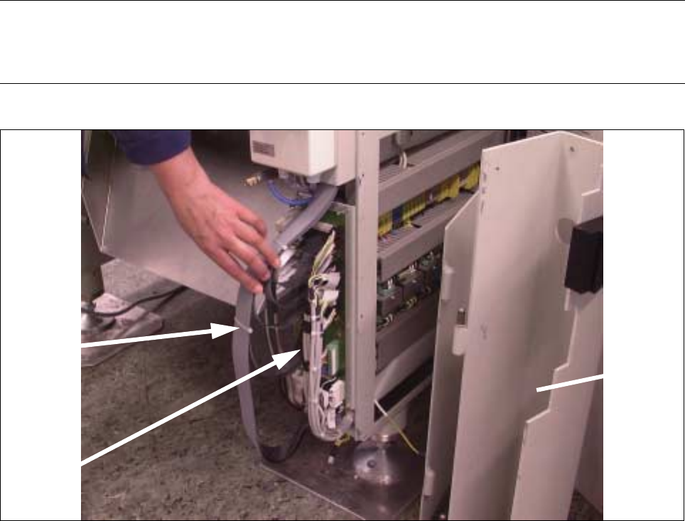
Fig. 5.7.6 Removing Ribbon Cable Ties, Disconnecting Plug-In Connections on the board
● Carefully remove the ties on the ribbon cable package (see Fig. 5.7.6 -> 1).
● Disconnect the plug-in connectors of the ribbon cable coming from the trailing cable (see Fig. 5.7.6 ->
2). The markings on the board and the cables define the allocations.
3 cable
ties
Gantry
board
Side guard
(dismantled)
SIPLACE 80S-20/F4/F4-6/F5 Service Manual 5 Gantries
Edition 09/99 5.7 Exchanging the X-/Y-Trailing Cable
5 - 31
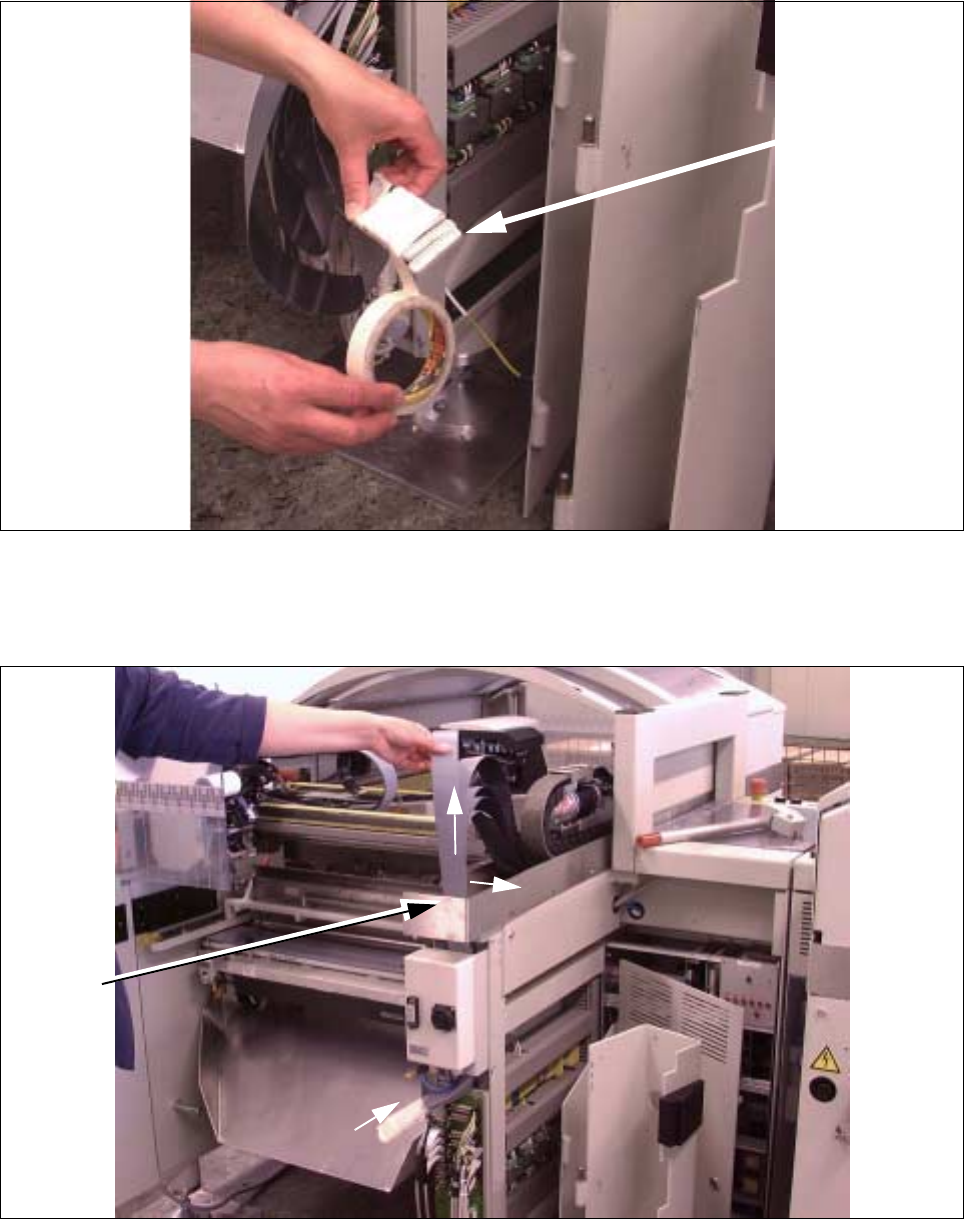
Fig. 5.7.7 Putting Connectors Side by Side and Wrapping Them with Masking Tape
● Prepare the ribbon cables for disassembly as shown:
Place the ribbon cables precisely side-by-side and wrap them with Masking tape.
Fig. 5.7.8 Unhooking Ribbon Cable Package on Cable Hanger and Pulling It Up and Out
● First pull the entire ribbon cable package up sideways out of the cable hanger and the top and then care-
fully and completely out the top as shown in Fig. 5.7.8 (Pos. 1, 2).
Ribbon cable
connection
(side-by-side)
2
2
1
Cable
hanger