80S-20贴片机.pdf - 第140页
5 Gantries SIPLACE 80S-20/F4/F4-6/F5 Service Manual 5.7 Exchanging the X -/Y-Trailing Cable Edition 09/99 5 - 32 5.7.6.3 Y- Gantry Area : Loos ening the Pneuma tic Hoses Fig. 5.7.9 Loosening Connections on the Pneumatic …
SIPLACE 80S-20/F4/F4-6/F5 Service Manual 5 Gantries
Edition 09/99 5.7 Exchanging the X-/Y-Trailing Cable
5 - 31
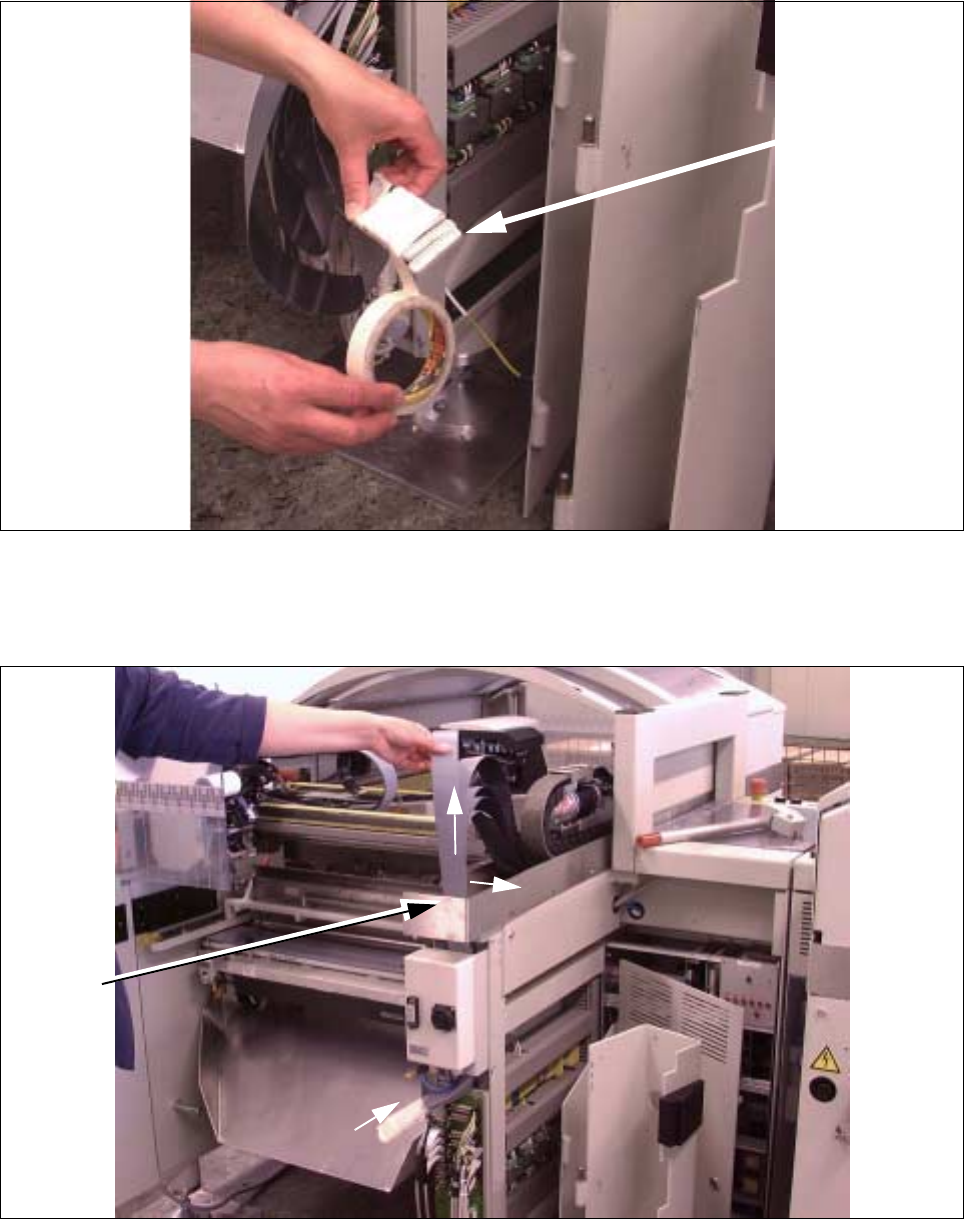
Fig. 5.7.7 Putting Connectors Side by Side and Wrapping Them with Masking Tape
● Prepare the ribbon cables for disassembly as shown:
Place the ribbon cables precisely side-by-side and wrap them with Masking tape.
Fig. 5.7.8 Unhooking Ribbon Cable Package on Cable Hanger and Pulling It Up and Out
● First pull the entire ribbon cable package up sideways out of the cable hanger and the top and then care-
fully and completely out the top as shown in Fig. 5.7.8 (Pos. 1, 2).
Ribbon cable
connection
(side-by-side)
2
2
1
Cable
hanger
5 Gantries SIPLACE 80S-20/F4/F4-6/F5 Service Manual
5.7 Exchanging the X-/Y-Trailing Cable Edition 09/99
5 - 32
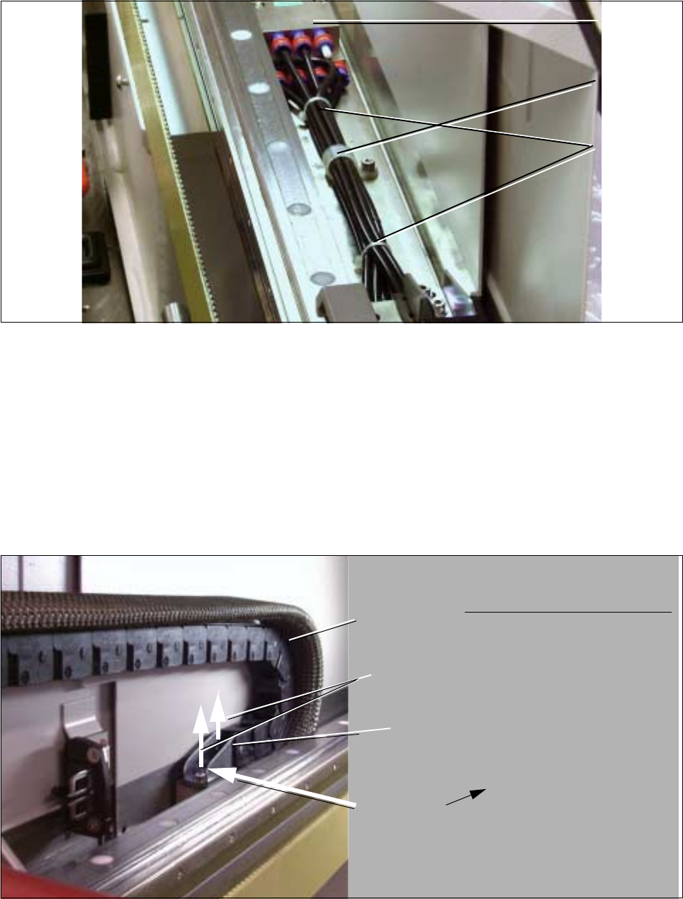
5.7.6.3 Y-Gantry Area: Loosening the Pneumatic Hoses
Fig. 5.7.9 Loosening Connections on the Pneumatic Block and Hose Clamps
● Loosen all the ties and hose clamps on the hose package (M3 screw: see Fig. 5.7.9). On the S20: 1 cable
clamp, 2 hose clamps; On F4 / F5: 2 cable clamps and 4 hose ties.
● Loosen all pneumatic connections on the air distributor block (see Fig. 5.7.9).
This is accomplished by pushing the red ring in the direction of the block.
5.7.6.4 Y-Gantry Area: Loosening the Pneumatic Hoses
Fig. 5.7.10 Loosening the Screws Fastening the Cable Supply Chain; Removing the Y-Strain Relief Device under It
(Example S-20, Gantry 2)
Air
distributor
block
Hose clamp
Cable ties
Cable supply
Two M 4 screws
U-bracket
Y-strain relief
chain
device
Top View: Y-Strain Relief Device
SIPLACE 80S-20/F4/F4-6/F5 Service Manual 5 Gantries
Edition 09/99 5.7 Exchanging the X-/Y-Trailing Cable
5 - 33
● Undo the two M 4 socket hex cap screws on the bracket of the cable supply chain (see Fig. 5.7.10).
● On the “Y-strain relief device” under the bracket, undo the 2 screws (size 3 Allen wrench) and remove the
horizontal reversing pin which relieves the strain (use size 1.5 Allen wrench as a drift punch).
● Remove the “Y-strain relief device”. Afterwards the cable supply chain and the ribbon cable strand will be
loose.
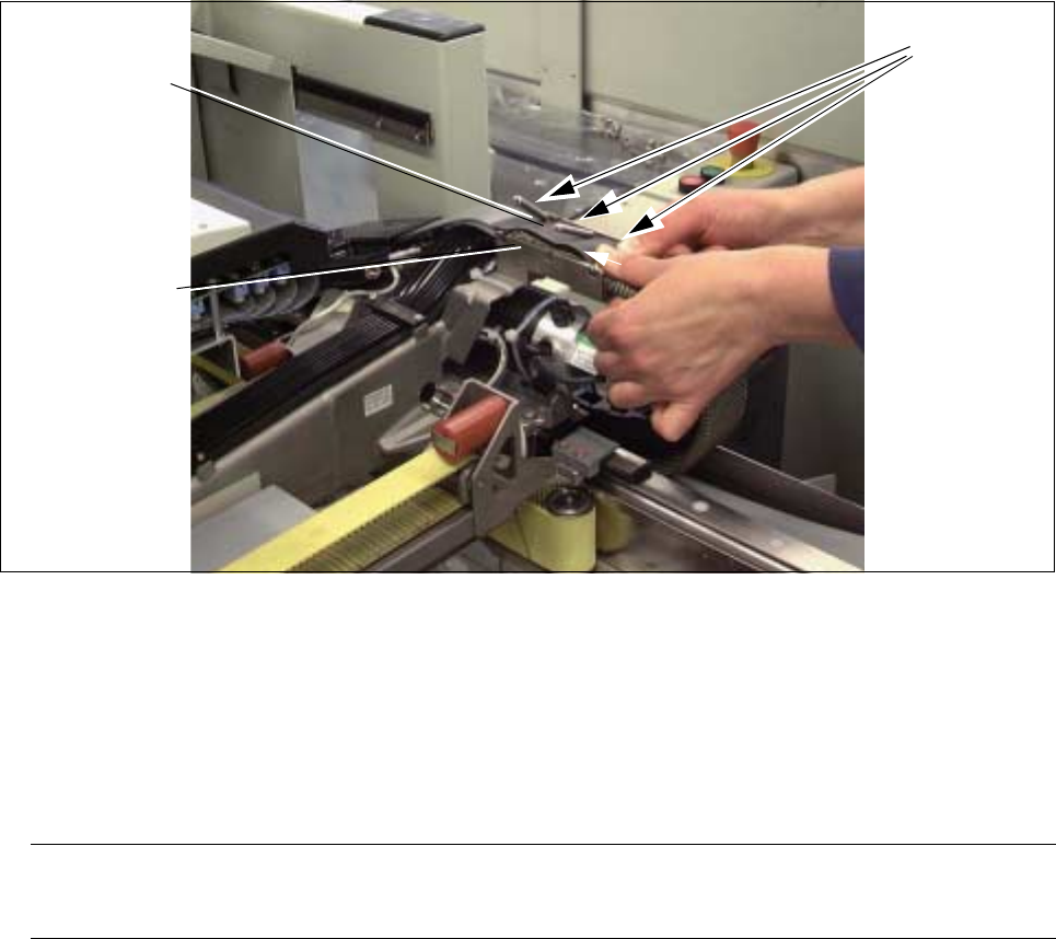
Fig. 5.7.11 Loosening the Fasteners of the Protective Hose on the Y-trailing cable hanger and Removing the Protective Hose
● Loosen the fasteners holding the protective hose at the trailing cable hanger (see Fig. 5.7.11), by pressing
the 3 pins into the slot area one after the other.
● Remove the 3 pins and the thin rubber sheet under it and the single section of ribbon cable. Be careful not
to lose any parts.
● Remove the protective hose:
NOTE
Do not cut the protective hose with scissors, otherwise fibers from the hose may get into the machine.
- Push the fabric protective hose together from the top (diameter will expand). Then, from the top, push
the protective hose from the cable/hose package down in the direction of the wrapped ribbon cable
connectors.
- Machine option F5 DCA: As described for the fabric protective hose, remove the polyester protection
by pulling it down.
● Pull the ribbon cable package up out of the inside of the machine base.
● If you only have to replace the protective hose, no further assembly work is required. In this case,
proceed to Section 5.7.7.1.
Pins
Y-trailing cable
hanger
Rubber sheet
and
piece of
ribbon cable