80S-20贴片机.pdf - 第143页
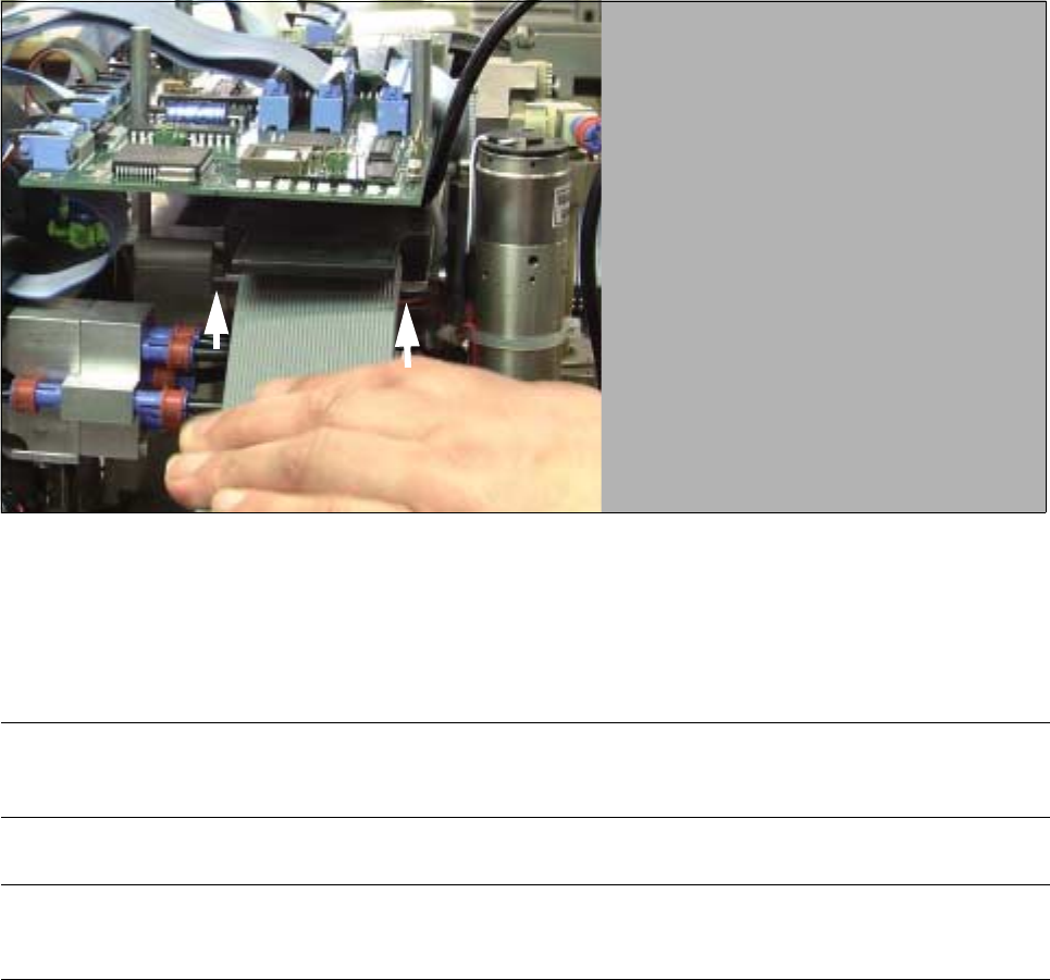
SIPLACE 80S -20/F4/F4-6/F5 Service Manual 5 Gantries Edition 09/99 5.7 Exchanging the X-/Y-Trailing Cable 5 - 35 5.7.6.6 X-Gantry Area: Dismantling the Ribbon Cables and/or Pneumatic Hoses Fig. 5.7.13 Loosening the Three…
5 Gantries SIPLACE 80S-20/F4/F4-6/F5 Service Manual
5.7 Exchanging the X-/Y-Trailing Cable Edition 09/99
5 - 34
5.7.6.5 Y-Gantry: Loosening Ribbon Cables on the “Large Axis” Board
Fig. 5.7.12 Removing the Cover on the “Large Axis” Conversion Board" and Pulling Off the Plug-In Connectors
WARNING O O
Comply with the regulations on ESDs (see Section 1 of this service manual).
● Remove the cover over the “Large Axis” conversion board (3 screws, size 2.5 Allen wrench).
● Pull both ribbon cable connectors off the board.
Conversion board
“Large Axis”
2 cables from
the Y-trailing
Studs, fasteners
three M 3 socket
hex screws
for cover:
cable:
Unplug
connector
SIPLACE 80S-20/F4/F4-6/F5 Service Manual 5 Gantries
Edition 09/99 5.7 Exchanging the X-/Y-Trailing Cable
5 - 35
5.7.6.6 X-Gantry Area: Dismantling the Ribbon Cables and/or Pneumatic Hoses
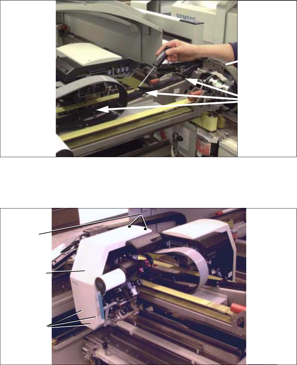
Fig. 5.7.13 Loosening the Three Retaining Blocks (Holddown) Along the X-Axis
● Remove the 3 holddowns from the X-axis (loosen two M3 socket hex cap screws holding each: see Fig.
5.7.13). Put down all of the components including the screws outside the X-gantry area, e.g. on the cover
of the input unit.
Fig. 5.7.14 Removing the Cover of the Pertinent Revolver Head
● Comply with the regulations on ESDs (see WARNING below):
Dismantle the cover from the revolver head (4 or 5 screws, depending on the model; size 2.5 Allen wrench:
see Fig. 5.7.14). In the case of the S-20, it is dismantled from the pertinent revolver head.
3 holddowns for
X-trailing cable
Y-trailing cable
(dismantled)
Two M 2
Three M 3
Cover for
revolver head
M2
screws
5 Gantries SIPLACE 80S-20/F4/F4-6/F5 Service Manual
5.7 Exchanging the X-/Y-Trailing Cable Edition 09/99
5 - 36
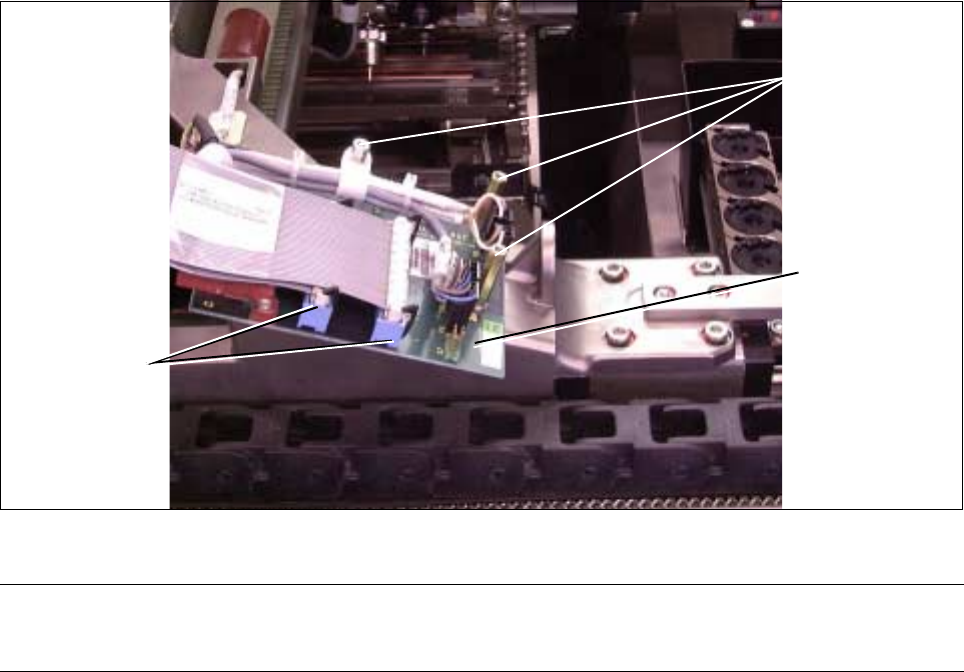
Fig. 5.7.15 Loosening the Counterstay (X-Cable Clamp) for X-Trailing Cable, Unplugging Ribbon Cable from Board
● Loosen the counterstay of the X-trailing cable under the “Small Axis” conversion board (loosen 2 screws
from the bottom, size 2.5 Allen wrench: see Fig. 5.7.15).
l Loosen plug-in connectors on the “Small Axis” conversion board (head board):
WARNING O O
Comply with regulations on ESDs (see Section 1 of this service manual.
NOTE
If only the 7-tube pneumatic hose is exchanged, skip the next 3 steps.
● Loosen the fasteners or the “Small Axis” conversion board at the studs (3 screws, size 2.5 Allen
wrench: see Fig. 5.7.2).
● Carefully tip the side of the board up and carefully pull all of the plug-in connectors of the X-trailing
cable off the bottom of the board.
● As a precautionary measure, fasten the board with at least one screw in the interim.