80S-20贴片机.pdf - 第148页
5 Gantries SIPLACE 80S-20/F4/F4-6/F5 Service Manual 5.7 Exchanging the X -/Y-Trailing Cable Edition 09/99 5 - 40 ● Place the ribbo n cables on top of o ne anot her in th e correct order. (a total of 8 on F4/F5 and 7 on t…

SIPLACE 80S-20/F4/F4-6/F5 Service Manual 5 Gantries
Edition 09/99 5.7 Exchanging the X-/Y-Trailing Cable
5 - 39
5.7.7.2 X-Gantry Area: Installing New Ribbon Cables and Pneumatic Hoses
Starting from the placement head, connect and run the cables and hoses exactly. This will enable you to
accommodate the resultant remaining length of the ribbon cable package behind the side guard.
Comply with the NOTE in Section 5.7.5.
● If you install a new, 7-tube pneumatic hose (Item No.: see Section 5.7.2), first perform the following
steps:
● Separate the hoses for the connection in the placement head area only at the upper end at first as
executed at the old hose.
● Using the disassembled 7-tube hose as a model, cut the separated new hoses for the head area in
appropriate lengths and at right angles.
To allocate the lengths, refer to the hose numbers (if imprinted) on the hoses. If the numbers for
tubes 1 to 7 are missing, at least mark No. 1 in the end areas of the tubes as specified in Fig. 5.7.18
(e.g., with labeled insulating tape, etc.).
Fig. 5.7.18 S-20 and F4/F5: Overview: Correctly Inserting and Connecting the 7-Tube Pneumatic Hose

5 Gantries SIPLACE 80S-20/F4/F4-6/F5 Service Manual
5.7 Exchanging the X-/Y-Trailing Cable Edition 09/99
5 - 40
● Place the ribbon cables on top of one another in the correct order.
(a total of 8 on F4/F5 and 7 on the S-20)
- The sequence of the long cables is indicated by the ID marking on the conversion boards (“Small
Axis” (head board) and/or on the gantry board.
Long cable lying in the X-axis area, top => top connector of the gantry board.
- The 2 short ribbon cables are not inserted until later (from above onto the Y-trailing cable).
● Run the 7-tube pneumatic hose in the correct rotational position (Nos. 1 to 7):
- S-20 and F4/F5: Hose No. 7 is next to the (possibly corresponding) revolver head (see Fig. 5.7.18).
● Place the top end of the cable/hose package in the guide of the counterstay (X-cable clamp), below the
conversion board “Small Axis”.
In the area of the counterstay (X-cable clamp) the position of the 7-tube pneumatic hose is below.
● Assemble the counterstay but tighten the 2 screws (size 2.5 Allen wrench: see Fig. 5.7.2) just enough
that the cables and hoses can still be moved.
NOTE
Take the diagram of the pneumatic system of S-20 or F4/F5, as applicable, out of the latest current diagram
folder so that it can be consulted whenever necessary.
● S-20: Connecting pneumatic system to the revolver head (see Fig. 5.7.16 and Fig. 5.7.18):
● Connect the five 5.5 bar hoses (Nos. 3 to 7) on the vacuum generator of the relevant revolver head to
the quick-release fasteners and clamp the latter with the red ring.
The allocations of Nos. 3 to 7 are of no concern because the 5.5 bar pressure is distributed centrally.
● Run hoses No. 1 and 2 (not under pressure on S-20) down the side of the revolver head (see Fig.
5.7.16) and tie these hoses together with cable ties. The ends of the hoses are placed behind the
cross member of the revolver head.
● F4/F5: Connecting pneumatic system to revolver head and IC head (see Fig. 5.7.17 and Fig. 5.7.18):
● Connect the five hoses Nos. 3 to 7 (5.5 bar) to the vacuum generator of the revolver head (quick-
release fasteners).
● Connect hoses No. 1 and 2 to the IC head:
- No. 1: for 2.3 bar -> to the solenoid for Z-axis clamping unit, to the quick-release fasteners
(see Fig. 5.7.17). Slip up the red ring to clamp on the hose.
- No. 2: for 5.5 bar -> to the vacuum generator, to the Y-connecting piece: see Fig. 5.5.17).
Slide the hose on correctly.
● Make certain that all hose connections are securely seated.
● Make the 2 plug-in connections on the conversion board “Small Axis” (head board):
● Reloosen the fasteners holding the board and carefully tilt the board lengthwise.
● Make the plug-in connections with the set of ribbon cables.
● Check the allocation of the connectors on the basis of the ID marking and make certain that the con-
nectors are securely seated.
● Fasten the conversion board “Small Axis” (3 screws, size 2.5 Allen wrench: see Fig. 5.7.2).
SIPLACE 80S-20/F4/F4-6/F5 Service Manual 5 Gantries
Edition 09/99 5.7 Exchanging the X-/Y-Trailing Cable
5 - 41
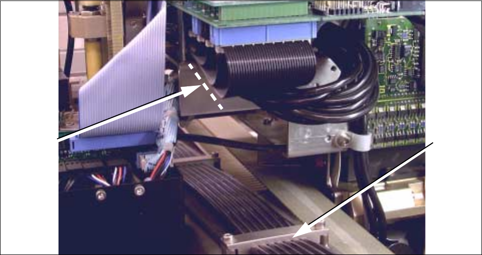
Fig. 5.7.19 Making the Plug-In Connections on the “Small Axis” board, Laying Ribbon Cable
● Pull the ribbon cables and the 7-tube hose down so that no large loops are left under the board in the head
area (see Fig. 5.7.19).
- Do not subject the hose and plug-in connections to any strain.
● Fasten the hose cable package in this position by tightening the counterstay.
● Run the X-trailing cable in the correct looping curve from the counterstay to X-gantry:
- The size of the imprint the 1st holdown made on the dismantled trailing cable may serve as an indica-
tor of the size of the loop.
- The 7-tube pneumatic hose must exactly follow the loop of the ribbon cable package.
- The loop of the X-trailing cable must be adjusted to the min. and max. travel position as shown in
Fig. 5.7.2 dargestellt. To adjust and check the position, move the placement head by hand.
- In the position 2 of the X-gantry shown in Fig. 5.7.2 he hose must fit closely against the ribbon cable
package but is not to exert pressure on it.
- In Pos. 1 there will be a small space between the ribbon cable package and the 7-tube pneumatic
hose because the end of the loop is shorter in this position.
● Fasten the X-trailing cable (cable/hose package) in the position determined, using the 3 holddowns on
the X-axis (2 screws each, size 2.5 Allen wrench: see Fig. 5.7.2 and Fig. 5.7.19).
Holddown
Correct
laying for
cable