80S-20贴片机.pdf - 第162页
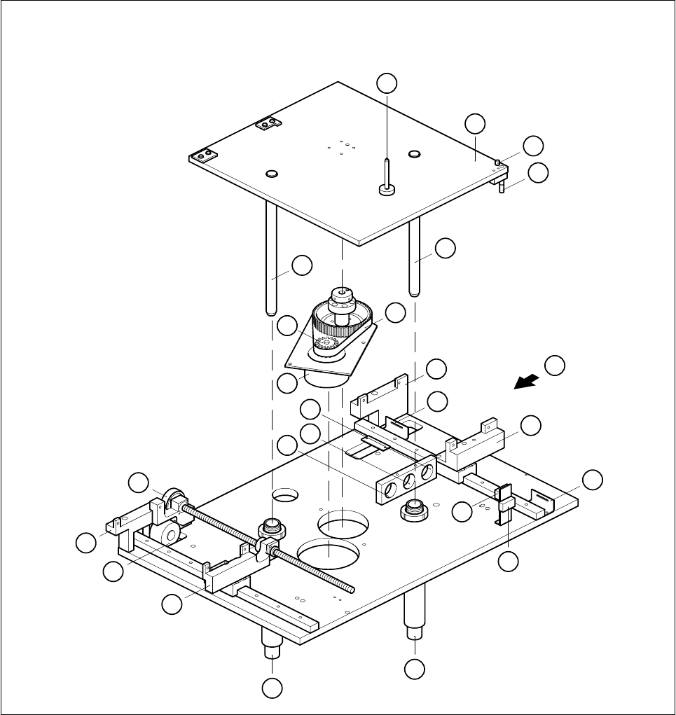
6 PCB Handling SIPLACE 80S-20/F4 Service Manual 6.1 Introduction Edition 01/96 6 - 6 Fig. 6.1.2 Lift ing table and width adjustment 1 12 3 4 6 7 5 8 9 10 12 13 14 15 16 17 18 19 20 21 22 4 A 2 11
SIPLACE 80S-20/F4 Service Manual 6 PCB Handling
Edition 01/96 6.1 Introduction
6 - 5
Key to Fig. 6.1.1
Key to Fig. 6.1.2
A Direction of board transport B Direction of movement of width adjustment
C Detailed view of board stopper D Board stopper basic module
E BERO F Sonar BERO
GValve
1 Input conveyor 2 Center conveyor
3 Output conveyor 4 Board stopper
5 Screws mounting the conveyor assemblies
onto the slide unit and onto the base unit
(in each case 2 M5 hexagon socket screws)
6 Conveyor side
7 Rocking lever 8 Movable side of conveyor
9 Guide rails for the board stopper 10 BERO for width adjustment
11 Slide unit (transportation support) 12 Base unit, fixed side, right (transportation support)
13 Mounting plate 14 Lifting table plate
15 Guide columns in the lifting table plate
1 Lifting table plate 2 Actuator for top microswitch
3 Actuator for bottom microswitch 4 Guide column
5 Synchroflex 16T5/455 toothed belt 6 Base, fixed side, righthand
7 Minimum board conveying width limit switch 8 Slide unit
9 Maximum board conveying width limit switch 10 Lifting table range limit switch, bottom
11 Lifting table range limit switch, top 12 Guide tube
13 Slide unit 14 Width adjustment stepping motor
15 Base, fixed side, righthand 16 Synchroflex 10T2.5/230 toothed belt
17 Mounting hole for sonar BERO evaluation
unit (output conveyor)
18 Mounting hole for sonar BERO evaluation unit
(input conveyor)
19 Mounting hole for sonar BERO evaluation
unit (center conveyor)
20 Lifting table motor
21 ALT5/Z16 synchronizing disk 22 Board support
A Direction of board transportation
6 PCB Handling SIPLACE 80S-20/F4 Service Manual
6.1 Introduction Edition 01/96
6 - 6
Fig. 6.1.2 Lifting table and width adjustment
1
12
3
4
6
7
5
8
9
10
12
13
14
15
16
17
18
19
20
21
22
4
A
2
11

SIPLACE 80S-20/F4 Service Manual 6 PCB Handling
Edition 01/96 6.2 Geared Motors of the PCB Transportation Systems
6 - 7
6.2 Geared Motors of the PCB Transportation Systems
6.2.1 Replacing the input and center conveyor geared motors
Spare parts, auxiliary materials and equipment
Geared motor with synchronizing disk, Item No. 00324405-01
SITEST program
6.2.1.1 Removing the geared motor from the input and output conveyors
NOTE OOO
You should also comply with the safety instructions given in Chapter 1.
● Select the maximum width setting for the board conveyor so that you can carry out servicing work unim-
peded.
● Move the gantry or gantries to outside the board transportation area.
● Switch off the machine at the main switch and disconnect it from the main power supply.
● Make sure that the machine cannot be switched on while you are carrying out servicing work.
● Mark the installed position of the geared motor and also label the cable connections as protection against
incorrect polarity upon reinstallation.
● Remove the cable shoes from the motor terminals.
● From the conveyor motor strip the heat-shrinkable sleeves which fasten the connecting cable.
● Unscrew and remove the 4 mounting screws (4 M3 slotted head screws) of the geared motor (A).
● Tilt the geared motor a little to one side while carefully pulling the geared motor backwards and out (B).
Make sure that the synchronizing disk does not catch in the toothed belt.