80S-20贴片机.pdf - 第188页
6 PCB Handling SIPLACE 80S-20/F4 Service Manual 6.7 Lifting Table Edition 01/96 6 - 32 Fig. 6.7.1 Removing the li fting t able Key to Fig. 6.7.1 6.7.2 Fitting the lifting table ● Insert the guide c olum ns into th e guid…

SIPLACE 80S-20/F4 Service Manual 6 PCB Handling
Edition 01/96 6.7 Lifting Table
6 - 31
6.7 Lifting Table
6.7.1 Removing the lifting table
NOTE OOO
You should also comply with the safety instructions in Chapter 1.
● Select the maximum width setting for the Board conveyor so that you can carry out servicing work unim-
peded.
● Move the gantry or gantries to outside the board transportation area.
● Switch off the machine at the main switch and disconnect it from the main power supply.
● Make sure that the machine cannot be switched on while you are carrying out servicing work.
● Slacken off the M 1.5 hexagon socket screws at the rocking levers and remove the ball bearing (A).
● Lift the lifting table plate vertically upwards and off (B).
CAUTION OO
The lifting table plate is heavy.
● Make sure that you do not tilt the lifting table as you lift it out, otherwise you may bend the guide columns.
● Set the lifting table plate face downwards on a flat and clean surface.
NOTE O
Do not place the lifting plate on its side. Do not rest it on the guide columns. This could bend the guide col-
umns.
6 PCB Handling SIPLACE 80S-20/F4 Service Manual
6.7 Lifting Table Edition 01/96
6 - 32
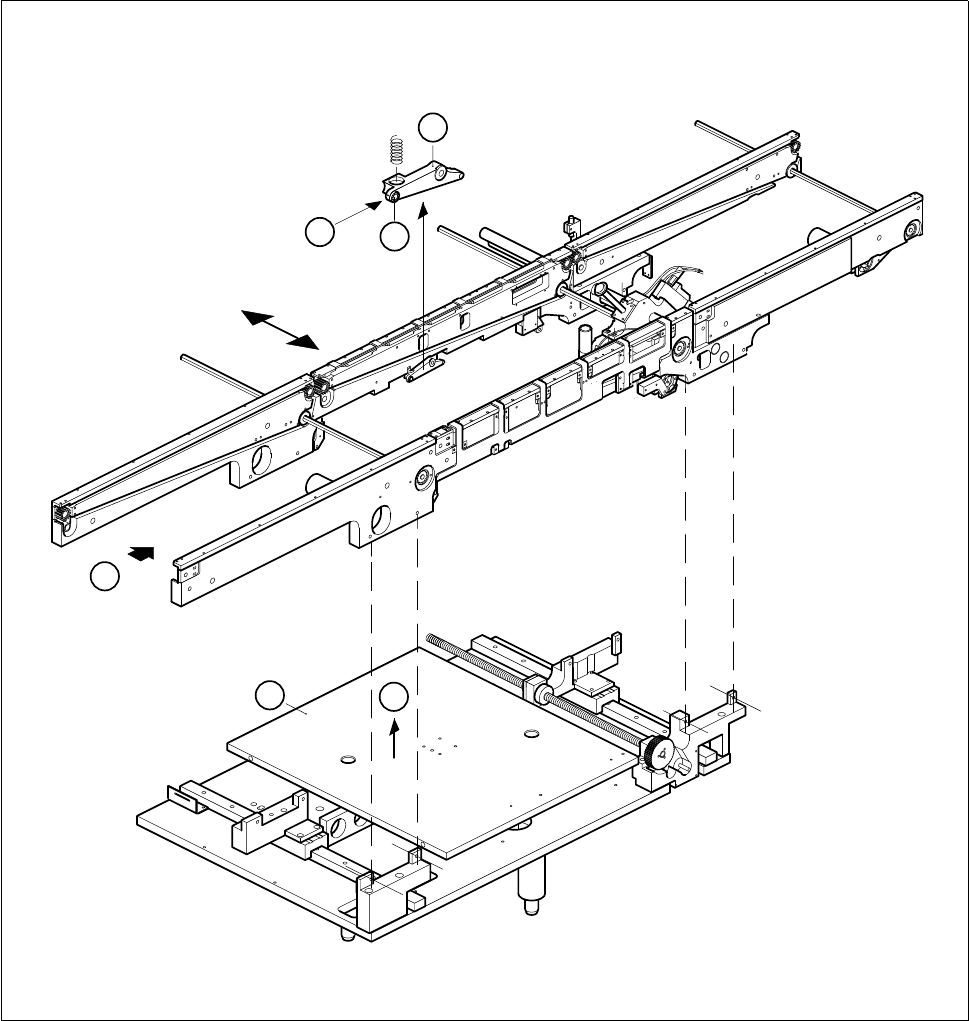
Fig. 6.7.1 Removing the lifting table
Key to Fig. 6.7.1
6.7.2 Fitting the lifting table
● Insert the guide columns into the guide tubes (A).
● Allow the lifting table to slide slowly downwards.
1 Rocking lever 2 Ball bearing
3 Lifting table
T Direction of board transport
3
T
B
A
2
1
SIPLACE 80S-20/F4 Service Manual 6 PCB Handling
Edition 01/96 6.7 Lifting Table
6 - 33
● Make sure the parallel pin on the lifting table plate is in line with the groove of the spindle stop (B).
● Make sure the lifting table plate sits on the spindle stop and the parallel pin engages in the groove.
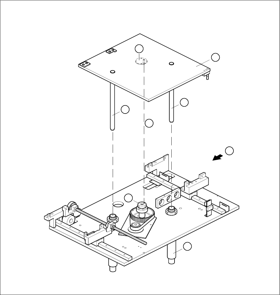
Fig. 6.7.2 Fitting the lifting table
Key to Fig. 6.7.2
● Fit the ball bearing on the rocking lever (see Fig. 6.7.1, Page 6 - 32, item (A), 1 and 2).
● Carry out a function test under the board conveyor menu.
1 Lifting table plate 2 Guide column
3 Bottom spindle stop 4 Parallel pin
5 Guide tube T Direction of board transport
1
2
2
T
5
4
B
3