80S-20贴片机.pdf - 第189页
SIPLACE 80S-20/F4 Service Manual 6 PCB Handling Edition 01/96 6.7 Lifting Table 6 - 33 ● Make s ure the p arallel pin on the lifting t able pl ate is i n line wi th the groo ve of t he spindle s top (B) . ● Make s ure th…
6 PCB Handling SIPLACE 80S-20/F4 Service Manual
6.7 Lifting Table Edition 01/96
6 - 32
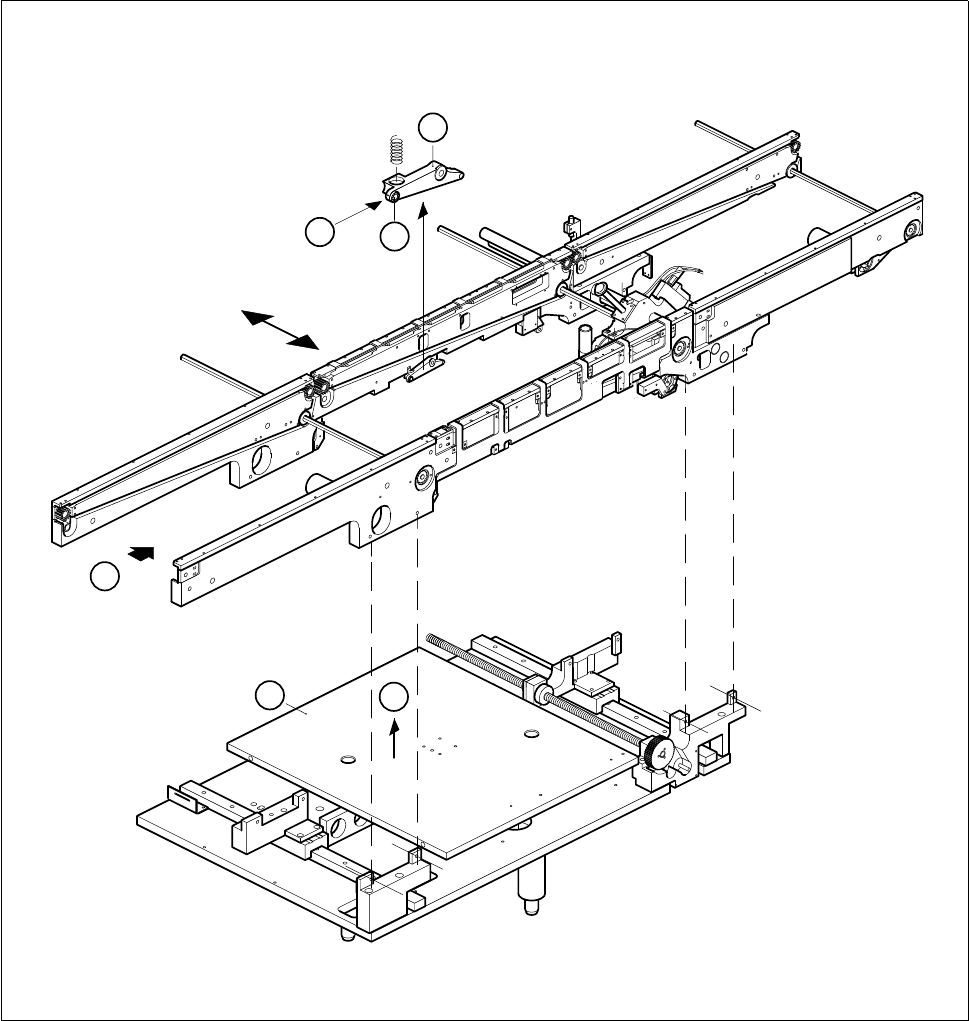
Fig. 6.7.1 Removing the lifting table
Key to Fig. 6.7.1
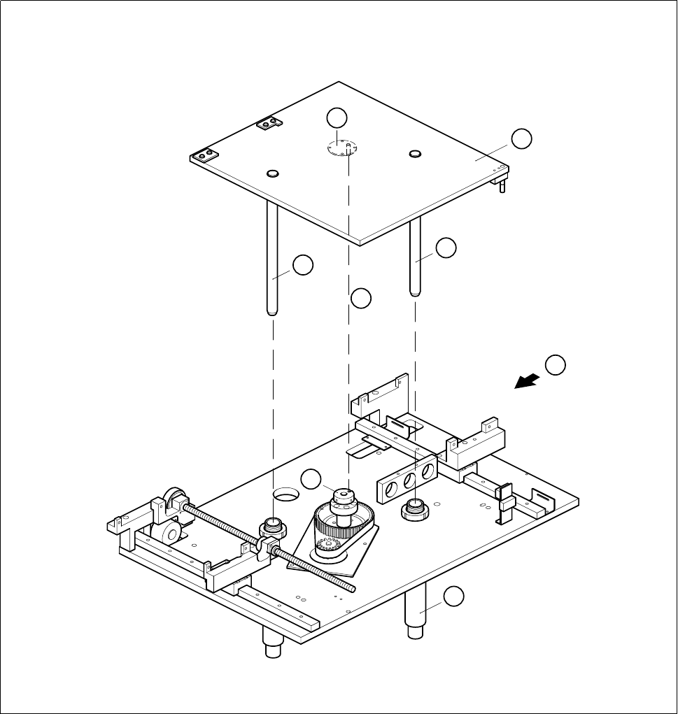
6.7.2 Fitting the lifting table
● Insert the guide columns into the guide tubes (A).
● Allow the lifting table to slide slowly downwards.
1 Rocking lever 2 Ball bearing
3 Lifting table
T Direction of board transport
3
T
B
A
2
1
SIPLACE 80S-20/F4 Service Manual 6 PCB Handling
Edition 01/96 6.7 Lifting Table
6 - 33
● Make sure the parallel pin on the lifting table plate is in line with the groove of the spindle stop (B).
● Make sure the lifting table plate sits on the spindle stop and the parallel pin engages in the groove.
Fig. 6.7.2 Fitting the lifting table
Key to Fig. 6.7.2
● Fit the ball bearing on the rocking lever (see Fig. 6.7.1, Page 6 - 32, item (A), 1 and 2).
● Carry out a function test under the board conveyor menu.
1 Lifting table plate 2 Guide column
3 Bottom spindle stop 4 Parallel pin
5 Guide tube T Direction of board transport
1
2
2
T
5
4
B
3
6 PCB Handling SIPLACE 80S-20/F4 Service Manual
6.7 Lifting Table Edition 01/96
6 - 34
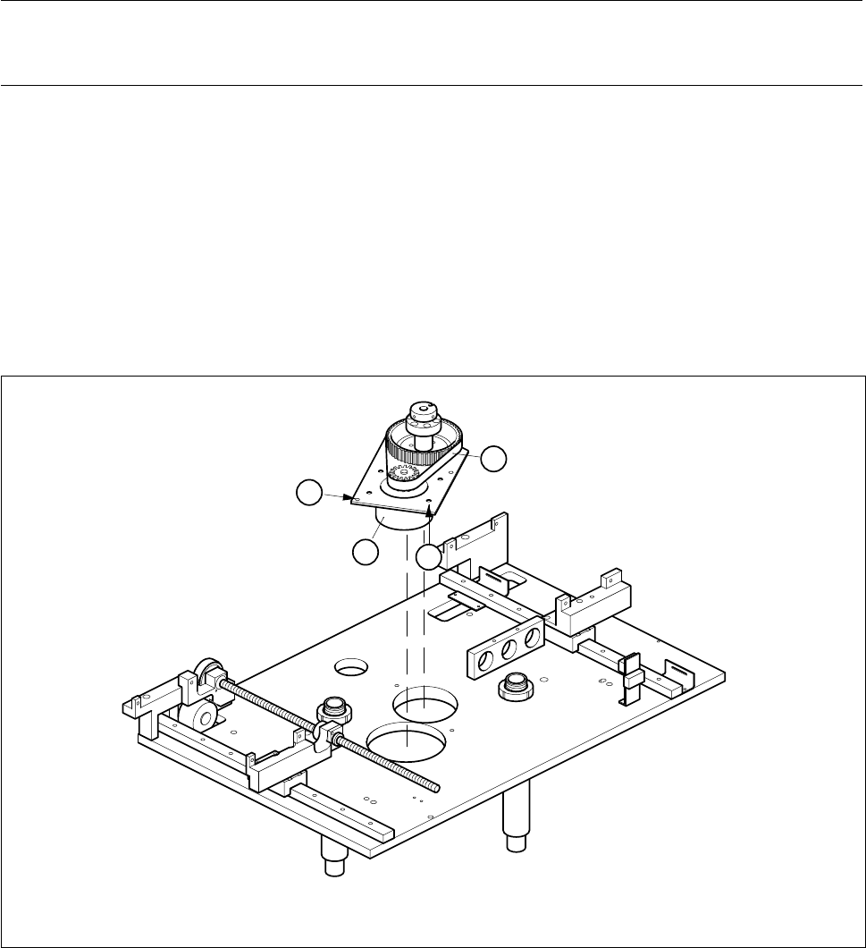
6.7.3 Replacing the lifting table motor
Spare parts, auxiliary materials and equipment
Lifting table motor, Item no. 00317887-02
SITEST program
6.7.3.1 Removing the lifting table motor
NOTE OOO
You should also comply with the safety instructions in Chapter 1 and Section 6.7.1, Page 6 - 31.
● Remove the lifting table as described in Section 6.7.1, Page 6 - 31.
● Undo the three M6 hexagon socket screws (A) in the drive base plate.
● Carefully lift the lifting table drive out and place it on the mounting plate with the top side facing down-
wards.
● Undo the four M6 hexagon socket screws which fasten the motor (B).
● Pull the lifting table motor power cable out of the cable ducts.
● Disconnect the cable ends from terminals 7, 8, 9 and 10 of terminal strip X1ro of the ’Lifting table stepping
motor A7’ conversion unit.
● Pull the cable out of the insulated through-hole in the drive base plate.
Fig. 6.7.3 Removing the lifting table motor
1 Lifting table motor 2 Synchroflex toothed belt
B
2
1
A