80S-20贴片机.pdf - 第191页
SIPLACE 80S-20/F4 Service Manual 6 PCB Handling Edition 01/96 6.7 Lifting Table 6 - 35 6.7.3.2 Fi tting the lifting table motor Fit the li fting tabl e motor i n the rev erse sequ ence o f operati ons to re moving i t. N…
6 PCB Handling SIPLACE 80S-20/F4 Service Manual
6.7 Lifting Table Edition 01/96
6 - 34
6.7.3 Replacing the lifting table motor
Spare parts, auxiliary materials and equipment
Lifting table motor, Item no. 00317887-02
SITEST program
6.7.3.1 Removing the lifting table motor
NOTE OOO
You should also comply with the safety instructions in Chapter 1 and Section 6.7.1, Page 6 - 31.
● Remove the lifting table as described in Section 6.7.1, Page 6 - 31.
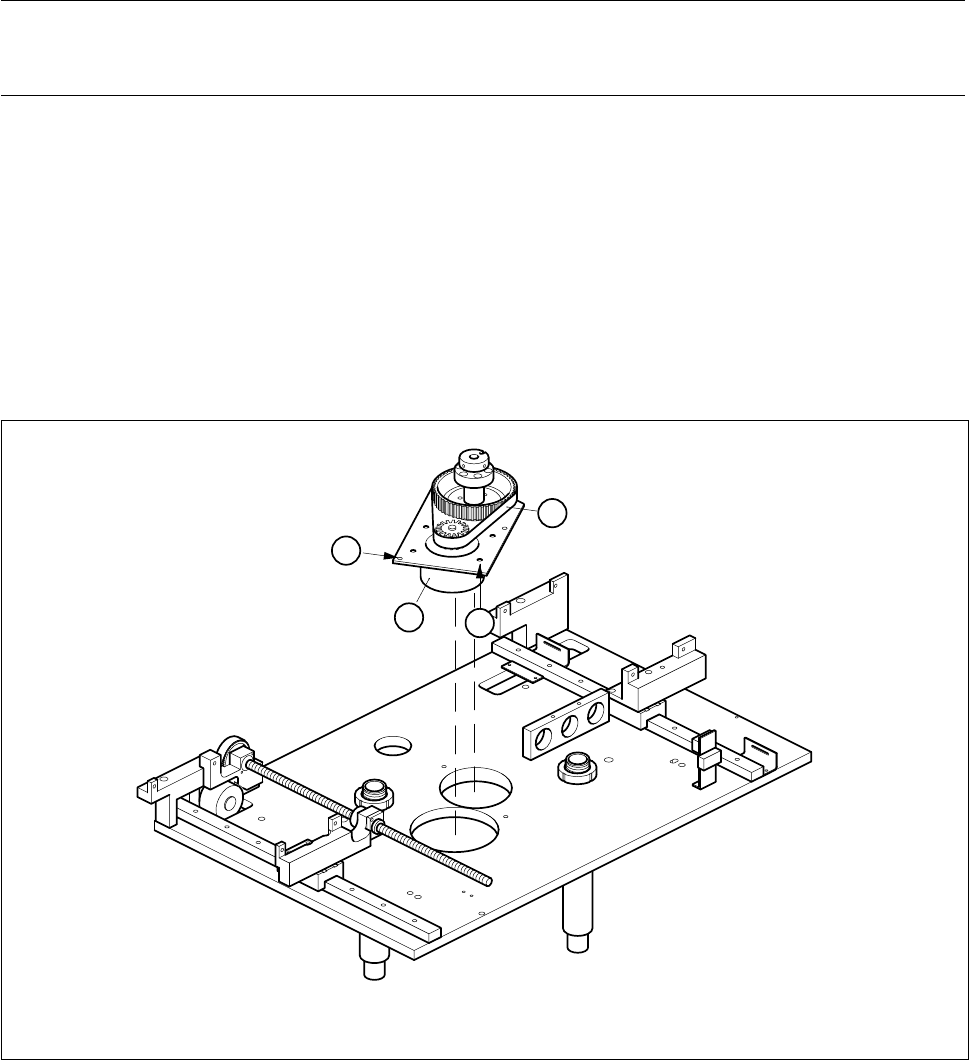
● Undo the three M6 hexagon socket screws (A) in the drive base plate.
● Carefully lift the lifting table drive out and place it on the mounting plate with the top side facing down-
wards.
● Undo the four M6 hexagon socket screws which fasten the motor (B).
● Pull the lifting table motor power cable out of the cable ducts.
● Disconnect the cable ends from terminals 7, 8, 9 and 10 of terminal strip X1ro of the ’Lifting table stepping
motor A7’ conversion unit.
● Pull the cable out of the insulated through-hole in the drive base plate.
Fig. 6.7.3 Removing the lifting table motor
1 Lifting table motor 2 Synchroflex toothed belt
B
2
1
A

SIPLACE 80S-20/F4 Service Manual 6 PCB Handling
Edition 01/96 6.7 Lifting Table
6 - 35
6.7.3.2 Fitting the lifting table motor
Fit the lifting table motor in the reverse sequence of operations to removing it.
NOTE O
With the aid of the circuit diagrams folder make sure that the colored wires of the power cable are connected
to the correct terminals in the terminal strip of the ’Lifting table stepping motor A7’ conversion unit.
● Install the lifting table plate as described in Section 6.7.2, Page 6 - 32.
6.7.3.3 Function test
Carry out setting and function testing with the aid of the adjustment instructions.
6.7.4 Replacing the toothed belt
Spare parts, auxiliary materials and equipment
Synchroflex toothed belt 16T5/455, Item No. 00317782-01
SITEST program
NOTE OOO
You should also comply with the safety instructions in Chapter 1 and Section 6.7.1, Page 6 - 31.
● Remove the lifting table as described in Section 6.7.1, Page 6 - 31.
● Remove the drive base plate as described in Section 6.7.3, Page 6 - 34.
● Slacken off the M6 hexagon socket screws of the lifting table motor.
● Replace the toothed belt (see Fig. 6.7.3, Page 6 - 34).
● Tighten up the mounting screws of the lifting table motor again.
● Attach the drive base plate.
● Install the lifting table plate as described in Section 6.7.2, Page 6 - 32.
● Carry out setting and function testing with the aid of the adjustment instructions.
6 PCB Handling SIPLACE 80S-20/F4 Service Manual
6.7 Lifting Table Edition 01/96
6 - 36
6.7.5 Replacing the lifting table limit switches
Spare parts, auxiliary materials and equipment
Lifting table limit switch, Item No. 00317892-03
NOTE OOO
You should also comply with the safety instructions in Chapter 1 and Section 6.7.1, Page 6 - 31.
● Remove the lifting table as described in Section 6.7.1, Page 6 - 31.
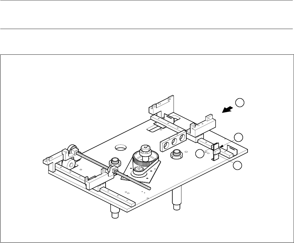
Fig. 6.7.4 Replacing the lifting table limit switch
Key to Fig. 6.7.4
● Use a pin to mark the precise position of the limit switch as installed (A).
● Unsolder the connection wires.
● Remove the limit switch and fit the new one at the place marked.
● Solder the connection wires on.
● Install the lifting table as described in Section 6.7.2, Page 6 - 32.
1 ’Lifting table at bottom’ limit switch 2 ’Lifting table at top’ limit switch
T Direction of board transport
1
2
A
T