80S-20贴片机.pdf - 第198页
6 PCB Handling SIPLACE 80S-20/F4 Service Manual 6.9 Sonar BER O Edition 01/96 6 - 42 ● Undo the c lamp holding th e sonar BERO (B) . ● Discon nect the s ensing h ead ca ble from the evalu ation uni t (C). Fig. 6.9.2 Remo…
SIPLACE 80S-20/F4 Service Manual 6 PCB Handling
Edition 01/96 6.9 Sonar BERO
6 - 41
6.9 Sonar BERO
Spare parts, auxiliary materials and equipment
Sonar BERO PCB input conveyor, new PCB handling, Item No. 00320862-01
Sonar BERO PCB center conveyor, new PCB handling Item No. 00320863-01
Sonar BERO PCB output conveyor, new PCB handling Item No. 00320864-01
Wrenches, width across flats 24 and 40, vernier calipers
6.9.1 Removing the sonar BERO unit
NOTE
The sonar BERO sensing head and the evaluation unit can only be replaced as a unit.
In addition, note the safety instructions in Chapter 1 and Section 6.7.1, Page 6 - 31.
● Remove the lifting table as described in Section 6.7.1, Page 6 - 31.
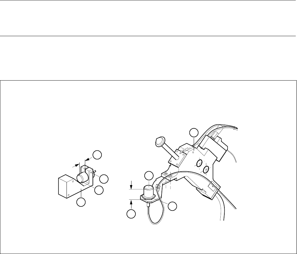
● With the vernier calipers measure the distance between the front face of the sonar BERO and the holder
(A).
Fig. 6.9.1 Removing the sonar BERO sensing head
Key to Fig. 6.9.1
1 Sonar BERO of input / output conveyors 2 BERO mount
3 Center conveyor sonar BERO 4 Board stopper
4
B
3
A
B
2
1
A
6 PCB Handling SIPLACE 80S-20/F4 Service Manual
6.9 Sonar BERO Edition 01/96
6 - 42
● Undo the clamp holding the sonar BERO (B).
● Disconnect the sensing head cable from the evaluation unit (C).
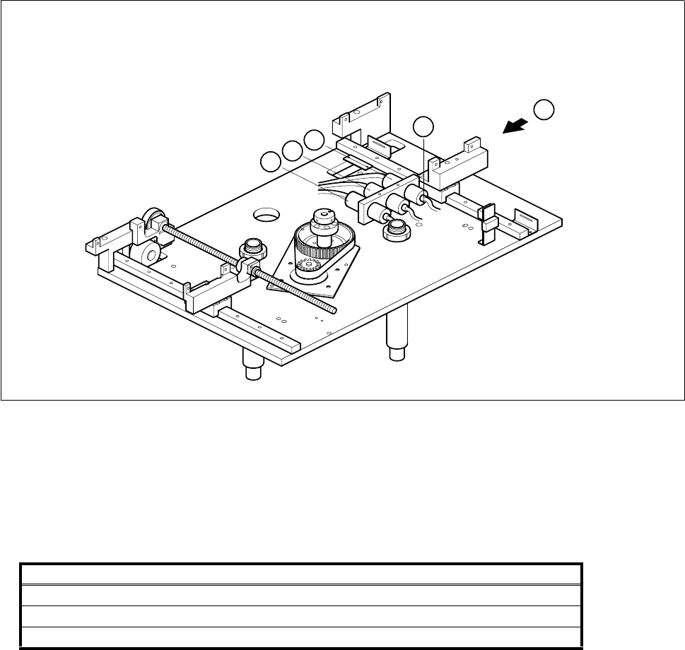
Fig. 6.9.2 Removing the sonar BERO evaluation unit
Key to Fig. 6.9.2
● Disconnect the connection cables of the evaluation units from the terminals of conversion unit II ’BEROS’,
A3, A4:
● Remove the sensing head and the evaluation unit.
6.9.2 Fitting the sonar BERO unit
● Fit the new BERO unit.
● With the aid of the circuit diagrams folder make sure that you have connected the unit up properly.
● Install the lifting table as described in Section 6.7.2, Page 6 - 32.
1 Output conveyor sonar BERO evaluation unit 2 Input conveyor sonar BERO evaluation unit
3 Center conveyor sonar BERO evaluation unit
Sonar BERO Terminal strip X1rp, terminals Cable
Input conveyor 1, 6, 15 Y461-W1
Center conveyor 2, 7, 16 Y462-W1
Output conveyor 3, 8, 17 Y463-W1
T
C
3
2
1
SIPLACE 80S-20/F4 Service Manual 6 PCB Handling
Edition 01/96 6.9 Sonar BERO
6 - 43
6.9.3 Adjustment and function test
● Lift the lifting table plate a little and hold the plate at this height with the aid of the board support.
● Switch the machine on and press the EMERGENCY STOP button.
● With the aid of the adjustment instructions carry out the required adjustments followed by a function test.