80S-20贴片机.pdf - 第205页
SIPLACE 80 S-20/F4 Service Manual 7 Components Table Edition 03/97 7.1 Overview 7 - 3 7.1 Ove rvi ew 7.1.1 Components T ables, Position and Connection Fig. 7.1.1 Overview: location of the components cha ngeover tables in…
7 Components Table SIPLACE 80 S-20/F4 Service Manual
Edition 03/97
7 - 2
SIPLACE 80 S-20/F4 Service Manual 7 Components Table
Edition 03/97 7.1 Overview
7 - 3
7.1 Overview
7.1.1 Components Tables, Position and Connection
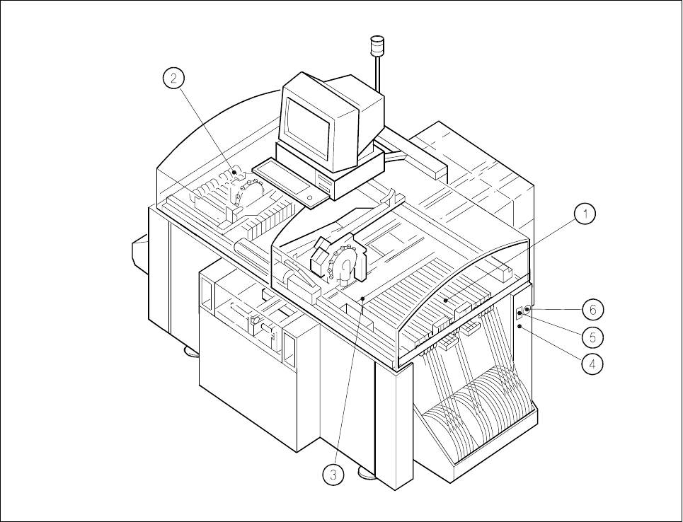
Fig. 7.1.1 Overview: location of the components changeover tables in the SIPLACE 80 S-20
Key to Fig. 7.1.1
1 Components changeover table with feeder modules, table 1, location 1 (tracks 1 to 120)
2 Components changeover table with feeder modules, table 2, location 3 (tracks 1 to 120)
3 Empty tape cutter unit (table 1)
4 Compressed air connection, components table pneumatic system, location 1
5 Interface connector for components supply location, connection of communications unit
6 Main power plug for connection of power supply (transformer) components table, location 1

7 Components Table SIPLACE 80 S-20/F4 Service Manual
7.1 Overview Edition 03/97
7 - 4
7.1.1.1 Mechanical Design
● In the SIPLACE 80 S machine the feeder modules are picked up on 2 "changeover components tables"
(table 1 and table 2).
● These changeover components tables are in each case mounted on a frame which also carries the com-
ponents table power supply (transformer T1), the communications unit, the tape container and the waste
tape container. This unit is designated the "components changeover table" (see Fig. 7.1.2).
● The "components changeover table" can be lifted by a lift truck and moved out of the machine (for details
on the procedure, see User Manual, Section 8).
● The defined position of the components table with respect to the machine base is ensured by the two dif-
ferently shaped centering pieces on the machine base which when the components table is lowered by the
lift truck move into the locating holes (press fit bushes) of the table (see Fig. 7.1.2). After it has been
placed in position, the components changeover table is held by means of 2 tensioning elements against
the support areas on the left and right of the machine base.
● Due to the precision of location required, it will not be necessary to check or reposition the track (machine
data) after replacement of the components changeover table.
● Definition of the locations for the SIPLACE 80 S can be seen in Fig. 7.1.1. Further details will be found for
example in section 5 "Data input" under "Components supply" in the user manual.
● The feeder modules are in each case connected by locating pins and spherical caps on the components
table (see Fig. 7.1.2) in a defined position and held in place by the magnetic strip.
● For the use of compressed air feeder modules (feeder modules using compressed air to convey) the "com-
ponents table compressed air supply unit" is fitted to the components table and the "pneumatic compo-
nents table" to the machine base - both as options (see Fig. 7.1.2).
● The empty tape channel of each location is screwed down to a rail and then fastened to the machine base
with the aid of this rail (see Fig. 7.1.3).
● The empty tape cutting unit is mounted with 2 brackets to the machine base (see Fig. 7.1.3).
7.1.1.2 Electrical / Pneumatic Systems
NOTE
An overview of the electrical system of the components changeover table will be found in the overview dia-
gram of the circuits folder.
● The "components changeover table" (see Fig. 7.1.2) has its own power supply (transformer T1, see Fig.
7.1.2) and its own controller (communications unit), which are connected as follows:
– Components table power supply → cable "Power" Y516-W1 or W2 → mains plug on the right-hand
side of the machine base (see Fig. 7.1.1),
– Communications unit → cable "Components table interface" Y559-W1 → plug X37 (interface right-
hand / left-hand), also on the right-hand side of the machine base, see Fig. 7.1.1.
● Components table-power supply: The transformer T1 is protected at the input end by fuse F1 with 3.16 AT
and the 8 VAC and 28 VAC voltages for the communications unit tapped off on the output side.
● Components feeder modules: The feeder modules are connected to the power supply at the connec-
tions panel of the communications unit: