80S-20贴片机.pdf - 第211页
SIPLACE 80 S-20/F4 Service Manual 7 Components Table Edition 03/97 7.1 Overview 7 - 9 7.1.4 Components T able Compr essed Air Supply Unit (Option) Fig. 7.1.4 Components table compressed air supply , top view When c ompre…
7 Components Table SIPLACE 80 S-20/F4 Service Manual
7.1 Overview Edition 03/97
7 - 8
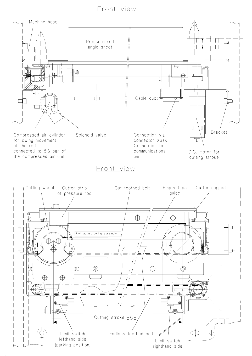
Fig. 7.1.3 Empty tape cutting unit : mounting in the machine base, structure and connections
SIPLACE 80 S-20/F4 Service Manual 7 Components Table
Edition 03/97 7.1 Overview
7 - 9
7.1.4 Components Table Compressed Air Supply Unit (Option)
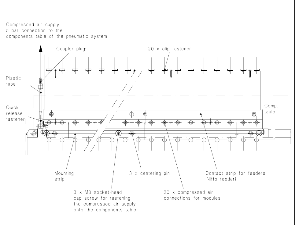
Fig. 7.1.4 Components table compressed air supply , top view
When compressed air feeder modules (= feeder modules which operate using compressed air) are to be used
the optional "components table compressed air supply unit" (see diagram above) together with the "compo-
nents table pneumatic system" (see Fig. 7.1.4) is installed in the SIPLACE 80 S machine.
● This "components table compressed air supply unit" (= compressed air distributor strip) is fitted in a
defined position on the longer side of the changeover components table (see Fig. 7.1.2) by means of 3
centering pins and fastened down to the components table with 3 socket-head cap screws M8.
● Each compressed air feeder module after installation at the components table is attached to the com-
pressed air distributor strip by means of a clip fastener. When the module is used the corresponding
plunger is pressed downwards into the compressed air distributor strip which assures continuous availabil-
ity of compressed air at the module.
● Connection to the power supply is at the corresponding socket on the connections panel (communications
unit).
● Actuation of the solenoid valves in the feeder module operates the compressed air branch in the module
and the components are conveyed onwards, separated into singles and brought into the pick-up position.
7 Components Table SIPLACE 80 S-20/F4 Service Manual
7.1 Overview Edition 03/97
7 - 10