80S-20贴片机.pdf - 第223页
SIPLACE 80 S-20/F4 Service Manual 7 Components Table Edition 03/97 7.5 Communications Unit 7 - 21 7.5 Communicat ions Un it 7.5.1 T ools and Spare Parts Required T ools ● Crosst ip screwdri ver , siz e 1 Auxiliary Meas u…
7 Components Table SIPLACE 80 S-20/F4 Service Manual
7.4 Flap Opener (Magazine Opener) Edition 03/97
7 - 20

SIPLACE 80 S-20/F4 Service Manual 7 Components Table
Edition 03/97 7.5 Communications Unit
7 - 21
7.5 Communications Unit
7.5.1 Tools and Spare Parts Required
Tools
● Crosstip screwdriver, size 1
Auxiliary Measuring and Test Equipment
● Feeder position tester, from item no. 00304770-03
● Ohmmeter
Spare Parts
● Back-up battery (battery, lithium), from item no. 00314295-03
● Communications unit complete, from item no. 00116013-04
● Control signals - components table cable, Y559-W1, from item no. 00300380-06
● Miniature fuse 5x20/T3, 16A / glass, from item no. 00304938-04
7.5.2 Fault Location and Correction
NOTE
With error Nos. 43 and 400 there could be a defect within the communications unit; with error No. 399 ("Pro-
gram loss of table and trolley control") it may be that only back-up battery of the processor board needs
replacing.
Start fault location by consulting the section Section 7.2 ’Fault Characteristics’.
The circuit diagrams for the communications unit ("Components table processor board" and "Components
table controller board") will be found in the current circuit diagrams folder.
If there is a defect in one of the boards then the complete communications unit will always be replaced.
7.5.2.1 Replacing the Back-Up Battery
With the error message "Program loss of table and trolley control" proceed as follows:
● Try to load the table once more. Select from within the "Machine errors menu" the menu item "Load table
program" → Return.
● If the error message "Program loss of table and trolley control" appears again, select "Abort placement" so
that all of the components picked-up at the placement heads in the course of the following reference run
can be returned. The placement heads travel to the stand-by position above the components loading point
in question (location 1 or location 3).
7 Components Table SIPLACE 80 S-20/F4 Service Manual
7.5 Communications Unit Edition 03/97
7 - 22
DANGER QQQ
Switch off the machine at the main switch and disconnect it from the main power supply.
● Pull out the plug X37 on the right-hand side of the machine base and also the power plug of the compo-
nents changeover table in question.
● Disconnect all plug connections of the modules at the connections panel of the communications unit:
The tapes must remain in position!
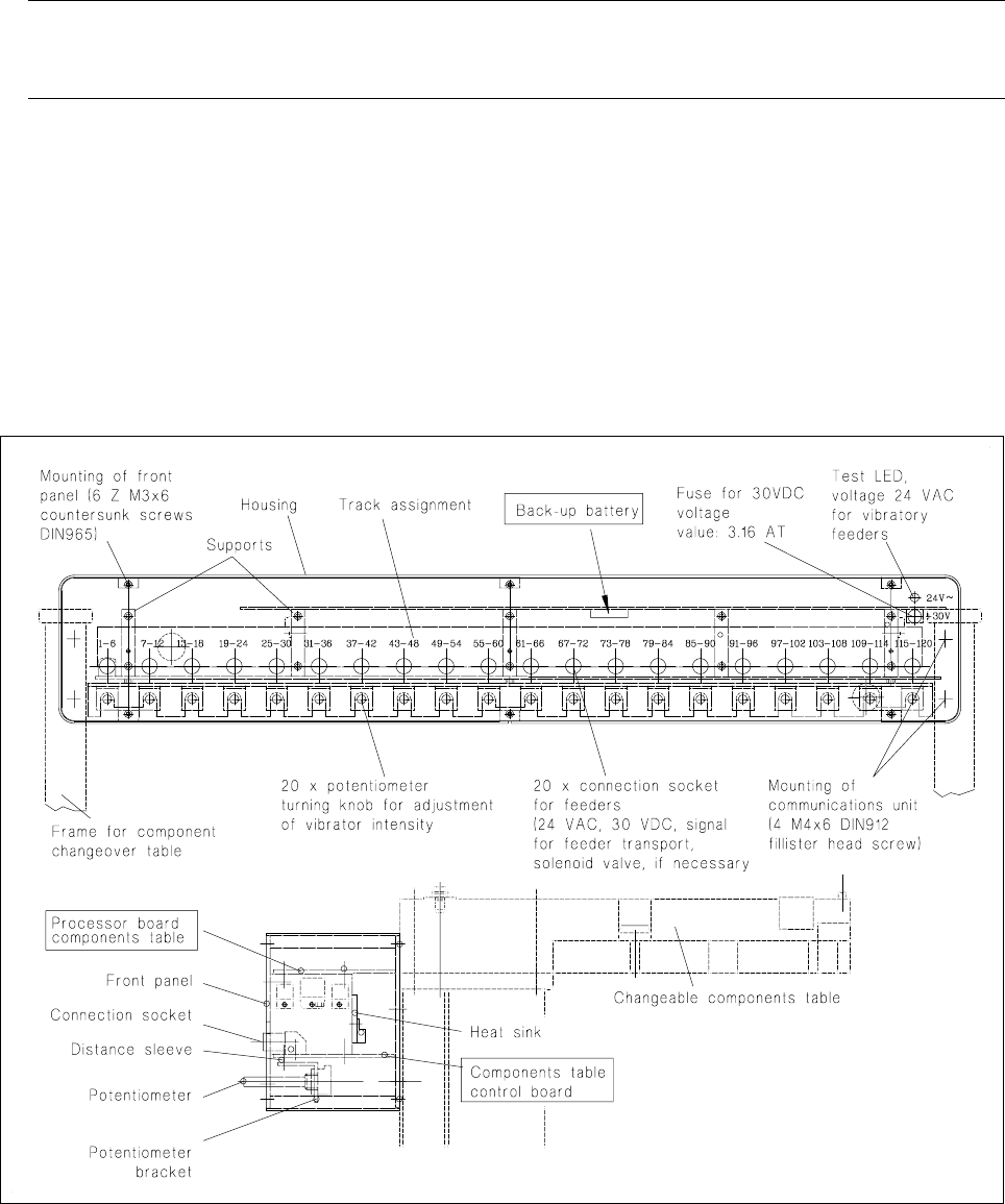
● Remove the front panel of the communications unit (6 recessed head screws M3).
● The back-up battery is located on the underside of the processor board = top board (see Fig. 7.5.1):
Slide the back-up battery forwards and out of its holder and slide in the new battery making sure the polar-
ity is correct: minus-pole points upwards! (see marking on the holder).
Fig. 7.5.1 Structure of the communications unit, replacement of the back-up battery
Refit the front panel and plug the feeder modules back into their connection sockets in the communications
unit.
● Reconnect the components changeover table back to plugs X37 and to the mains plug.
● Switch on the machine and start placement sequence. The components table will be loaded automatically
at the new start: in other words, the table program will be loaded into the memory of the components table
controller.