80S-20贴片机.pdf - 第256页
7 Components Table SIPLACE 80 S-20/F4 Service Manual 7.7 Components Table Pneum atics, Components Table Com pressed Air S upply Edition 03/97 7 - 54 – If you can not get the requi red 5 bar pr essure, r epla ce the pr es…
SIPLACE 80 S-20/F4 Service Manual 7 Components Table
Edition 03/97 7.7 Components Table Pneumatics, Components Table Compressed Air Supply
7 - 53
● Pull the plug of the compressed air feed module which is not conveying out of the connection socket of the
communications unit. The module remains in place at the components table.
● Connect the location tester to the connection socket of the communications unit which is now becoming
free. For detailed information on using the location tester, please refer to the Section 7.5 ’Communications
Unit’.
● You must now create the fault once again in order to set the output signal for the feed module.
● The assumption here is that when the "Track empty" error message is displayed, the track is not actu-
ally empty but that there is a pick-up error.
● When the "Track empty" error message is displayed select: Component feed → Fill all (setter pass-
word) → Return. The corresponding track errors will be deleted.
● Position the location tester so that you can read it easily. Start the placement sequence and by doing
so generate once more error No. 43. At the same time check the "A1" LED on the location tester:
– If the "A1" LED is not illuminated, this may indicate an interruption in the communications unit.
Proceed as described in the Section 7.5 ’Communications Unit’.
– If the "A1" LED of the location tester is on, this means the control signal is reaching the socket.
A fault in the compressed air feed module can be excluded by connecting it to the external power
supply (see section above), which will mean that there must be a fault in the 5 bar compressed air
branch. Continue work with the following section.
7.7.3 Fault Location and Correction: Compressed Air Unit and
Components Table Pneumatic System
● If you have already determined that the fault is not in the module or in the communications unit (see pre-
ceding section), select "Abort placement" in order that all of the components are returned which were
picked up at the placement heads during the course of the ensuing reference run. The placement heads
move into the waiting position above the corresponding components loading point.
● Remove the cover over the compressed air unit from the machine base (undo 2 special socket-head cap
screws using a size 3 socket spanner).
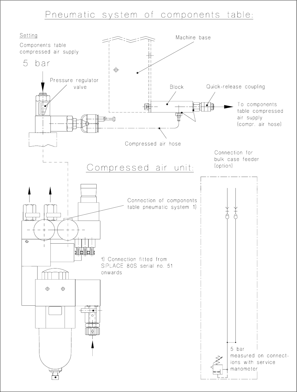
● Check the 5.6 bar operating pressure (see User Manual, Section 9).
● Check all of the screwed hose connections of the 5 bar compressed air branch which supplies the feed
module:
● At the pressure regulating valve of the compressed air unit (see Fig. 7.7.1),
● at the block, components table pneumatic system, on the right of the machine base (see Fig. 7.7.1)
and
● at the components table compressed air supply (see Fig. 7.1.4 in the section "Overview").
● If the air is leaking at the block, switch off the machine and replaced the damaged sealing rung (see Fig.
7.7.1).
● If there are no leaks at any point up to the connection to the components table compressed air supply,
switch off the machine at the main switch and then undo the threaded hose connection at the pressure reg-
ulating valve of the compressed air unit (for components table pneumatic system connections, see Fig.
7.7.1).
● Connect the service manometer by the threaded hose connection directly to the pressure regulating valve.
● Switch on the machine at the main switch (the control system remains off). Compressed air is on.
● The service manometer must show 5 bar precisely; if it does not, set the correct pressure using the adjust-
ment screw (screwdriver for socket-head screws):

7 Components Table SIPLACE 80 S-20/F4 Service Manual
7.7 Components Table Pneumatics, Components Table Compressed Air Supply Edition 03/97
7 - 54
– If you cannot get the required 5 bar pressure, replace the pressure regulating valve (after disconnect-
ing the machine from the power supply and compressed air network!) or inform the SMD Service
department of Siemens AG.
– If the compressed air was at the correct pressure, check the pressure at the block of the components
table pneumatic system (service manometer). If you measure a different value:
DANGER QQQ
Switch off the machine at the main switch and disconnect it from the main power supply.
● If necessary, check the compressed air hose which runs in the interior of the machine base. If the
compressed air hose is pinched, replace it. Fit the cable lacings back in place, reconnect the
compressed air hose to the block and to the components table compressed air supply.
● Connect the machine to the mains and switch on.
● Fit the cover to the machine base (size 3 screwdriver for socket-head screws).
● If you still have not been able to determine what the fault it, check the components table compressed air
supply unit.
SIPLACE 80 S-20/F4 Service Manual 7 Components Table
Edition 03/97 7.7 Components Table Pneumatics, Components Table Compressed Air Supply
7 - 55
Fig. 7.7.1 Testing the compressed air branch of the "Compressed air unit - components table pneumatic system"