80S-20贴片机.pdf - 第265页
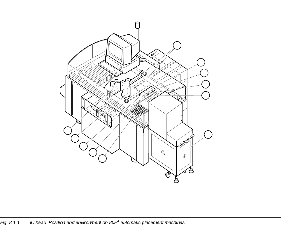
SIPLACE 80S-20/F4 Service Manual 8 IC Head Edition 01/97 8.1 Position and Environment of the I C Head 8 - 3 3RVLWLRQDQG(QY LURQPHQWRI WKH,&+HDG Key to Fig. 8.1.1 The S IPLACE 80 F 4 automatic placeme nt sys…
8 IC Head SIPLACE 80S-20/F4 Service Manual
Edition 01/97
8 - 2
SIPLACE 80S-20/F4 Service Manual 8 IC Head
Edition 01/97 8.1 Position and Environment of the IC Head
8 - 3
3RVLWLRQDQG(QYLURQPHQWRIWKH,&+HDG
Key to Fig. 8.1.1
The SIPLACE 80F
4
automatic placement system is equipped with a revolver placement head and an IC
placement head. Both placement heads are mounted on a common gantry.
The IC head is fixed to the gantry with two M4 x 16 or M4 x 25 fillister head screws. Two parallel pins ensure
that the IC head is mounted precisely on the gantry.
1 IC head 2 Revolver head
3 X/Y gantry system (gantry 1) 4 Nozzle changer for IC head
5 Flip-chip camera (option) 6 Reject container for IC head
7 Location 2: feeder module 8 Wafflepack changer (option)
9 Location 1: wafflepack magazine for WPC 10 Coplanarity laser module (option)
11 IC camera
8
7
6
5
4
3
9
10
11
1
2
8 IC Head SIPLACE 80S-20/F4 Service Manual
8.2 Structure and Functional Groups of the IC Head Edition 01/97
8 - 4
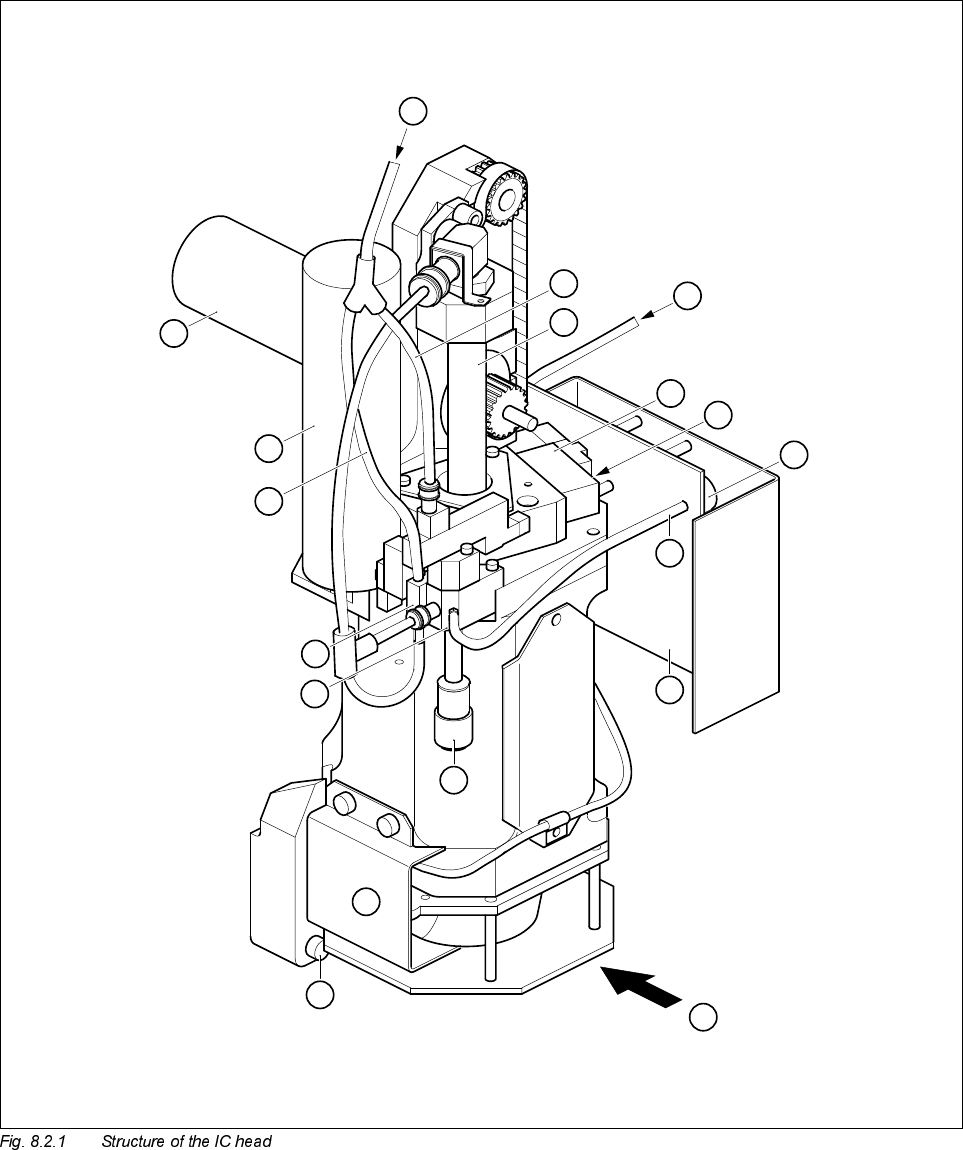
6WUXFWXUHDQG)XQFWLRQDO*URXSVRIWKH,&+HDG
1
2
3
A
5
7
6
8
B
9
10
11
12
13
14
15
16
4