80S-20贴片机.pdf - 第280页
8 IC Head S IPLACE 80S-20/F4 Service Manual 8.4 Servicing W ork on the Dr A xis Edition 01/97 8 - 18 Key to Fig. 8.4.2 ● Using th e ’Vision s ystem/te aching po sitio n’ menu, m ove the IC head ov er the IC h ead ca mera…
SIPLACE 80S-20/F4 Service Manual 8 IC Head
Edition 01/97 8.4 Servicing Work on the Dr Axis
8 - 17
&DOFXODWHWKH=HUR3RLQW&RUUHFWLRQIRUWKH'$[LV
PLEASE NOTE
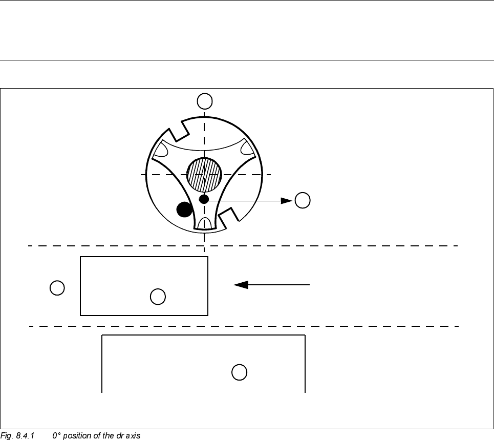
The starting value on the axis display should be approximately 0 if the pin of the nozzle support is pointing
towards component table no. 3.
Key to Fig. 8.4.1
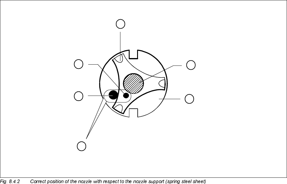
To accurately calculate the zero point correction value, you require the IC head camera and a type 416 noz-
zle.
● Place the nozzle in the correct position, as shown in Fig. 8.4.2.
● To ensure that the nozzle is clearly visible to the IC camera, mark the tip of the nozzle with washable white
paint.
A0° position of the dr axis
B The pin of the star should point towards component table 3
C PCB transport direction
D Component table 3
PCB
A
B
C
D
Table 3
8 IC Head SIPLACE 80S-20/F4 Service Manual
8.4 Servicing Work on the Dr Axis Edition 01/97
8 - 18
Key to Fig. 8.4.2
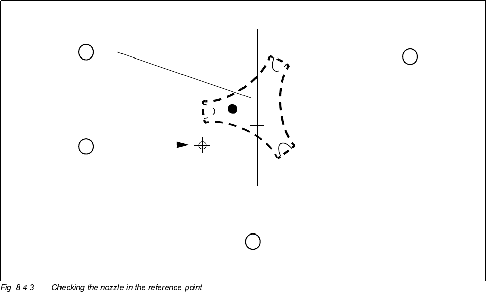
● Using the ’Vision system/teaching position’ menu, move the IC head over the IC head camera.
● Press F7 on the IC head camera to switch over.
● Disable the dr axis and align the nozzle over the red crosshairs.
1 Spring plate on the star (spring steel sheet) 2 Sleeve
3 Nozzle 4 Pin in the nozzle
5Pin
A The two pins must be opposite one another, with the pin of the nozzle lying against the spring plate.
A
2
4
3
5
1
SIPLACE 80S-20/F4 Service Manual 8 IC Head
Edition 01/97 8.4 Servicing Work on the Dr Axis
8 - 19
Key to Fig. 8.4.3
● The axis display should read 0 digits. If this is not the case, proceed as described for calculation of the zero
point correction for the z axis (see section 8.3.9, page 8 - 14).
ZPC
NEW
= ACTUAL - DESIRED + ZPC
OLD
ZKHUH'(6,5('
ZPC
NEW
= ACTUAL + ZPC
OLD
1 Station monitor 2 Stop pin on the nozzle
A Nozzle at IC head, dr axis 0° position
video image from IC camera
B Position of the rectangular nozzle, type 416
A
1
2
B