80S-20贴片机.pdf - 第283页
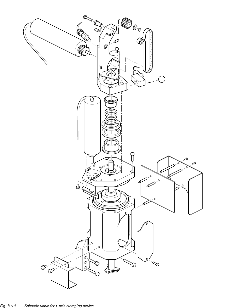
SIPLACE 80S-20/F4 Service Manual 8 IC Head Edition 01/97 8.5 Servicing Work on the Pneumatic System 8 - 21 Key to Fig. 8.5.1 1 Sole noid v alve for z axis cla mping device: Compres sed air su pply a t 2.3 ba r 1

8 IC Head SIPLACE 80S-20/F4 Service Manual
8.5 Servicing Work on the Pneumatic System Edition 01/97
8 - 20
6HUYLFLQJ:RUNRQWKH3QHXPDWLF6\VWHP
7RROV(TXLSPHQWDQG&RQVXPDEOHV
6SDUH3DUWV
5HSODFH6ROHQRLG9DOYHIRU=$[LV&ODPSLQJ'HYLFH
See item 1 in Fig. 8.5.1 page 8 - 21
● Loosen the two slotted screws that fix the solenoid valve in place.
● Remove the connecting cable.
● Fix the new solenoid valve in place and reconnect to the power supply.
PLEASE NOTE
The small red push-button is used only to manually actuate the solenoid valve, i.e. to release the clamping
device.
)URPLWHPQXPEHU
Hexagon socket head screw key, set
SITEST program
UNISILKON L250L 00310259-01
)URPLWHPQXPEHU
Valve (clamping device for z axis) 00306387-02
Valve (vacuum) 00306389-03
Valve (forced air) 00306388-02
Collet bush PK-3 00303552-01
O-ring 3 x 1 FPM 80SB 00301723-01
O-ring 5 x 1.5 NBR 70B 00305480-01
Vacuum nozzle for the IC head 00318370-01
O-ring 8 x 1 NBR 70B 00201179-01
Silencer G-1/8 CV05 HS 00308498-01
Hose connector T-PK-3 00303088-01
Nipple with male threaded end CN-M3-PK-3 00305374-01

8 IC Head SIPLACE 80S-20/F4 Service Manual
8.5 Servicing Work on the Pneumatic System Edition 01/97
8 - 22
5HSODFHWKH¶9DFXXP*HQHUDWRU21¶6ROHQRLG9DOYH
See items 1 and 2 in Fig. 8.5.2 page 8 - 23
This valve switches the 5.6 bar compressed air supply for the vacuum generator.
7RGLVDVVHPEOHWKHYDOYH
● Loosen the two 2.5 mm hexagon socket head screws that fix the block in place (item 2, Fig. 8.5.2).
● Loosen the two slotted screws that fix the solenoid valve in place on the block.
● Remove the air hose and the power cable.
7RUHDVVHPEOHWKHYDOYH
● Reverse the above sequence to assemble the valve.
PLEASE NOTE
On the underside of the valve, there is a white push-button for manually actuating the valve.
5HSODFHWKH¶)RUFHG$LU21¶6ROHQRLG9DOYH
See item 3, Fig. 8.5.2 page 8 - 23
● Loosen the two slotted screws that fix the valve in place.
● Remove the air hose and the power cable.
● Reverse the above sequence to assemble the valve.
The red push-button is used to manually actuate the valve.
&KHFNWKH9DFXXP6\VWHP
See Fig. 8.5.3 page 8 - 25
A drop in the vacuum generation performance may be caused by one of the following:
– The silencer (item 6) is dirty.
– The vacuum nozzle (item 4) is dirty.
– There is a leak in the pneumatic hose system.