80S-20贴片机.pdf - 第284页
8 IC Head S IPLACE 80S-20/F4 Service Manual 8.5 Servicing W ork on the Pneum atic System Edition 01/97 8 - 22 5HSO DFHWKH¶9 DFXXP*HQHUDWRU21¶6 ROHQRLG9 DOY H See item s 1 an d 2 in Fi g. 8.5.2 page 8 - 23 Th…

8 IC Head SIPLACE 80S-20/F4 Service Manual
8.5 Servicing Work on the Pneumatic System Edition 01/97
8 - 22
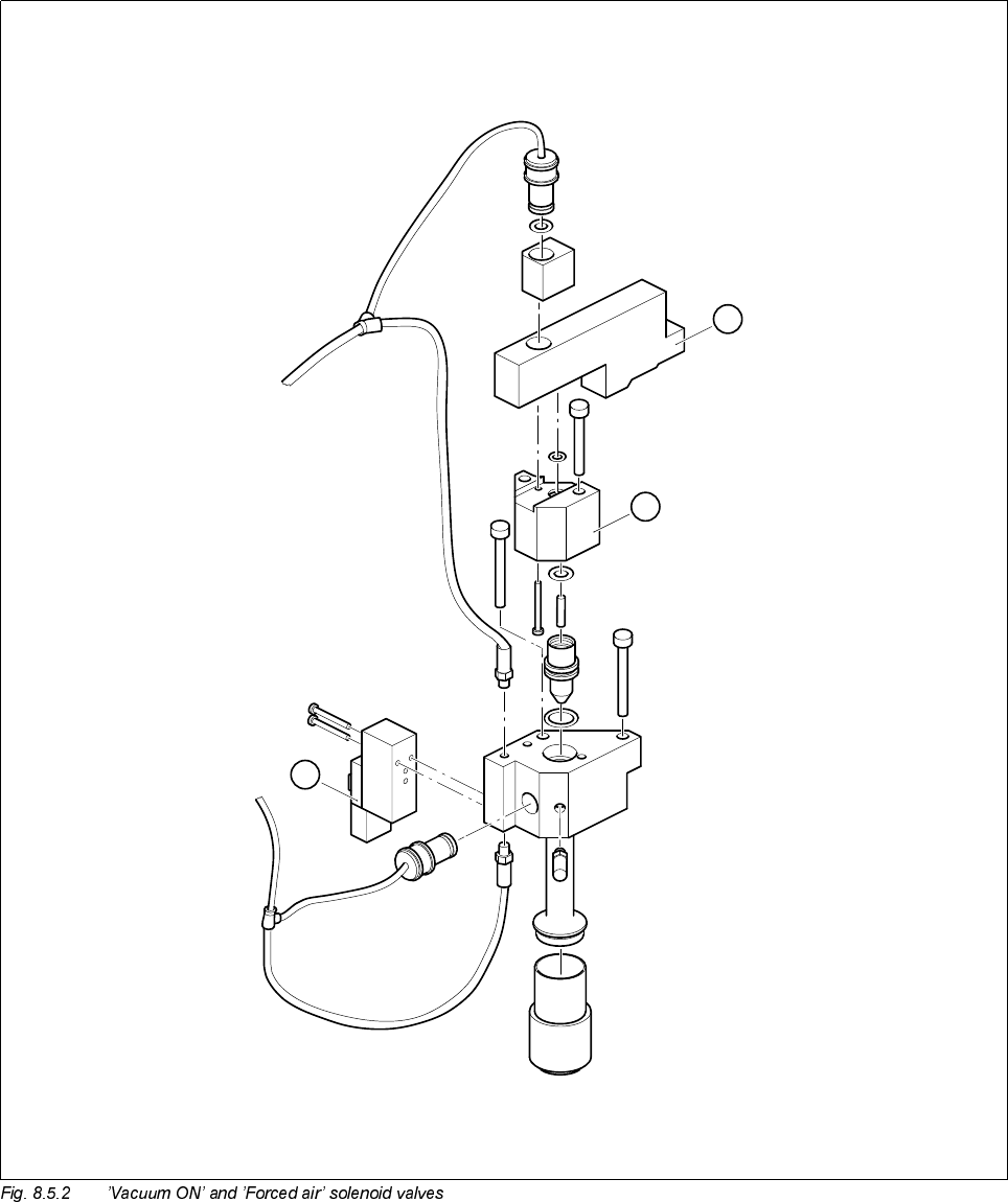
5HSODFHWKH¶9DFXXP*HQHUDWRU21¶6ROHQRLG9DOYH
See items 1 and 2 in Fig. 8.5.2 page 8 - 23
This valve switches the 5.6 bar compressed air supply for the vacuum generator.
7RGLVDVVHPEOHWKHYDOYH
● Loosen the two 2.5 mm hexagon socket head screws that fix the block in place (item 2, Fig. 8.5.2).
● Loosen the two slotted screws that fix the solenoid valve in place on the block.
● Remove the air hose and the power cable.
7RUHDVVHPEOHWKHYDOYH
● Reverse the above sequence to assemble the valve.
PLEASE NOTE
On the underside of the valve, there is a white push-button for manually actuating the valve.
5HSODFHWKH¶)RUFHG$LU21¶6ROHQRLG9DOYH
See item 3, Fig. 8.5.2 page 8 - 23
● Loosen the two slotted screws that fix the valve in place.
● Remove the air hose and the power cable.
● Reverse the above sequence to assemble the valve.
The red push-button is used to manually actuate the valve.
&KHFNWKH9DFXXP6\VWHP
See Fig. 8.5.3 page 8 - 25
A drop in the vacuum generation performance may be caused by one of the following:
– The silencer (item 6) is dirty.
– The vacuum nozzle (item 4) is dirty.
– There is a leak in the pneumatic hose system.