80S-20贴片机.pdf - 第310页
9 12-Segment Revolver Head (10000) SIPLACE 80S-20/F4 Service Manual 9.2 Replacing the Valve Adjustment Driv e for the Placement or Reject Circuits Edition 07/97 9 - 14 9.2.5 Replacing the T ooth ed Belt Spare par ts – Sy…
SIPLACE 80S-20/F4 Service Manual 9 12-Segment Revolver Head (10000)
Edition 07/97 9.2 Replacing the Valve Adjustment Drive for the Placement or Reject Circuits
9 - 13
9.2.4 Replacing the O-Ring
Spare parts
– O-ring 2x16 E 70B, from item no. 00320043-01
● Disconnect plug-in connections X10 and X12 from head board C0005.
● Undo the hexagon socket screw (M3 x 25) at the rear of the placement head and carefully pull the turning
station towards the rear and out (see Fig. 9.2.2).
● Carefully remove the toothed belt from the motor pinion by simultaneously turning and pulling at the belt
(see Fig. 9.2.3).
● Now change the o-ring 2x16 (see Fig. 9.2.3).
● To re-install the turning station, proceed in the reverse sequence of operations.
NOTE
No adjustments of settings are required after changing the o-ring.
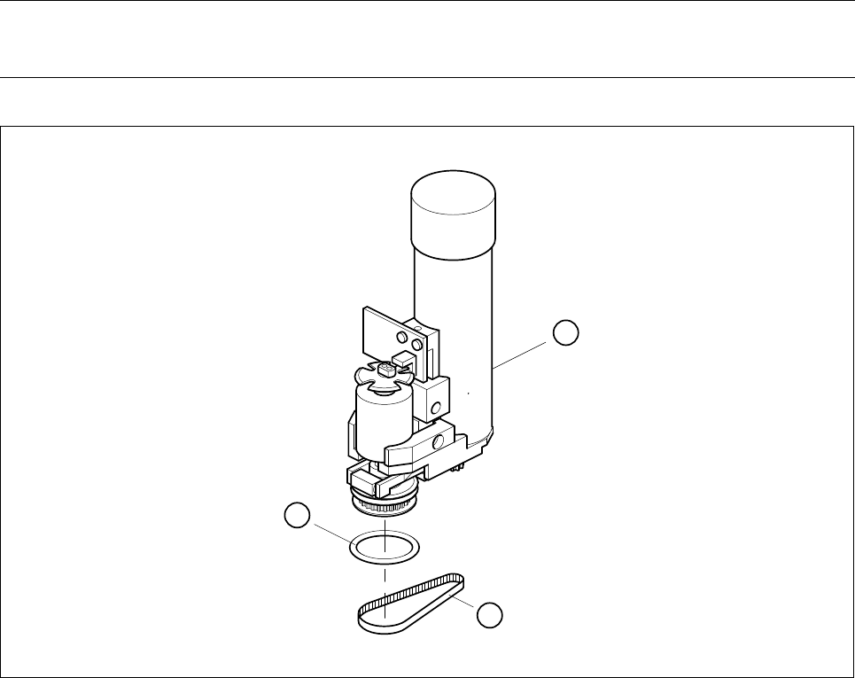
Fig. 9.2.3 Replacing the o-ring in the turning station
1 Turning station complete
2 O - ring 2x16
3 Toothed belt
2
3
1

9 12-Segment Revolver Head (10000) SIPLACE 80S-20/F4 Service Manual
9.2 Replacing the Valve Adjustment Drive for the Placement or Reject Circuits Edition 07/97
9 - 14
9.2.5 Replacing the Toothed Belt
Spare parts
– Synchroflex toothed belt, 2.5T2/90, from item no. 00320041-01
● Disconnect plug-in connections X10 and X12 from head board C0005.
● Undo the hexagon socket screw (M3 x 25) at the back of the placement head and carefully pull the turning
station towards the rear and out (see Fig. 9.2.2).
● Replace the toothed belt (see Fig. 9.2.3).
● To re-install proceed in the reverse sequence of operation.
NOTE
No adjustments of settings are required after changing the toothed belt.

Serviceanleitung SIPLACE 80S-20/F4 9 12er Revolverkopf (10000)
Ausgabe 07/97 9.3 Austausch der Verteilerplatine und der BE-Kamera
9 - 15
9.3 Austausch der Verteilerplatine und der BE-Kamera
9.3.1 Austausch der Zwischenverteilerplatine (Platine am Sternmotor)
HINWEIS
Diese Tätigkeit darf nur von Servicetechnikern der Fa. Siemens oder entsprechend geschultem Personal des
Kunden durchgeführt werden.
Ersatzteil
– Zwischenverteiler SP6/12, ab Artikel-Nr. 00321215S04
– Entfernen Sie die Steckverbindungen X13, X14 an der Kopf-Platine C0005.
● Lösen Sie die Innensechskantschraube (M3 x 8).
● Lösen Sie die drei Sechskantabstandshalter M3x7, M3x9 und M3x10 (siehe Abb. 9.3.1).
● Entfernen Sie die Steckverbindungen X3 bis X12 an der Verteilerplatine Y 0010 (siehe Abb. 9.3.1).
● Ziehen Sie vorsichtig den Schlauch vom Druckluftsensor ab.
● Beim Einbau gehen Sie in umgekehrter Reihenfolge vor.
● Nach dem Tausch der Zwischenverteilerplatine die Blaslufteinheit neu abgeglichen werden (siehe
”Abgleich der Blaslufteinheit”, Seite 9 - 30 ).
9.3.2 Austausch der BE-Kamera
Ersatzteile
– BE-Kamera 24x24, ab Artikel-Nr. 00320549S04
HINWEIS
Die BE-Kamera wird nur als komplette Einheit getauscht (Kamera, Verstärker, Beleuchtungssteuerung).
● Lösen Sie die Steckverbindung X3 an der Platine Y0021 (siehe Abb. 9.3.1).
● Entfernen Sie die vier Innensechskantschrauben (M4 x 10) und entnehmen Sie vorsichtig die BE-Kamera
(siehe Abb. 9.3.1).
● Beim Einbau gehen Sie in umgekehrter Reihenfolge vor.
ACHTUNG ∆
!
∆
!
Achten Sie beim Einsetzen der BE-Kamera auf saubere Anschlagflächen und einen genauen Sitz der Paß-
stifte. Ziehen Sie erst danach die Schrauben fest.
– Die weitere Vorgehensweise zum Kalibrieren der BE-Kamera entnehmen Sie der Anleitung Sitest.