80S-20贴片机.pdf - 第32页
1 Operational Safety SIPLACE 80S-20/F4/F4-6/F5 Ser vice Manual 1.3 Residual voltages i n the servo unit and discharge times when placement system is switched off Edition 04/98 1 - 22 1.3.1 Operating voltages, residual vo…
SIPLACE 80S-20/F4/F4-6/F5 Service Manual 1 Operational Safety
Edition 04/98 1.3 Residual voltages in the servo unit and discharge times when placement system is switched off
1 - 21
5HVLGXDOYROWDJHVLQWKHVHUYRXQ LWDQGG LVFKDUJH
WLPHVZKHQSODFHPHQWV\VWHPLVVZ LWFK HGRII
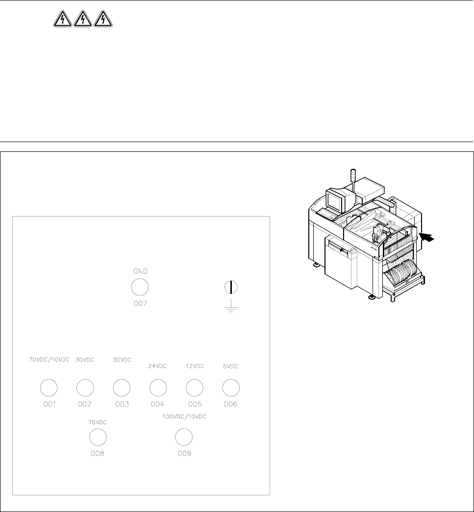
When the emergency stop button is pressed or the placement system is switched off, the electrolytic capaci-
tors quickly discharge to safe residual voltage levels via switched resistors on the discharge board
(00308443-xx).
The voltages can be tapped off at test sockets 001 - 009 on the voltmeter unit in the servo unit.
DANGER
Automatic placement systems from the SIPLACE family are powered with 3 x 400 V ± 10 %, 50/60 Hz mains
voltage.
This means that parts of the system carry potentially fatal voltages - even when switched off at the main
switch.
Death, serious injury or considerable damage may result if these placement systems are handled incorrectly.
Always follow the applicable accident prevention and VDE regulations (particularly VDE 0113).
The guard over the servo unit must ONLY be opened by appropriately qualified and trained personnel.
Fig. 1.3.1 Test sockets on the voltmeter unit in the servo unit
un-
switched
switched
Servo
unit
1 Operational Safety SIPLACE 80S-20/F4/F4-6/F5 Service Manual
1.3 Residual voltages in the servo unit and discharge times when placement system is switched off Edition 04/98
1 - 22
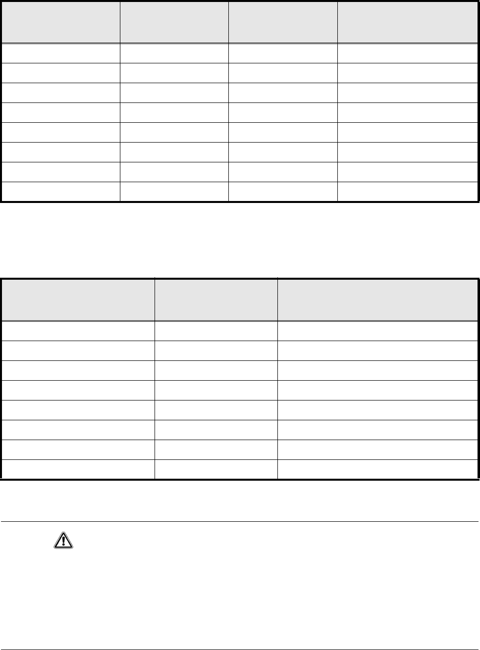
1.3.1 Operating voltages, residual voltages and discharge times after
pressing the emergency stop button
1.3.2 Residual voltages and discharge times after switching off at the
main switch
CAUTION
To avoid losing data, evaluate the following criteria before switching off your automatic placement system
(apart from in emergencies):
– Has the placement system finished transmitting machine, set-up and working data?
– Has the placement system finished processing the PCB?
– Has the placement system completed the run-up phase?
– Has the Windows NT operating system been shut down correctly?
7HVWVRFNHW;
PHDVXUHGDW
*1'
9ROWDJH
LQQRUPDOPRGH
5HVLGXDOYROWDJH
DIWHUHPHUJHQF\VWRS
'LVFKDUJHWLPHV
RIHOHFWURO\WLF
FDSDFLWRUVDW9'&
001 70 VDC 10 VDC < 2 sec
002 30 VDC 30 VDC –
003 30 VDC < 12 VDC < 2 sec
004 24 VDC 24 VDC –
005 12 VDC 12 VDC –
006 5 VDC 5 VDC –
008 70 VDC 10 VDC < 2 sec
009 100 VDC 10 VDC < 1 sec
Tab. 1.3 - 1 Operating voltages, residual voltages and discharge times after pressing the emergency stop button
7HVWVRFNHW;
PHDVXUHGDW*1'
5HVLGXDOYROWDJH
ZKHQPDLQVZLWFKLVRII
'LVFKDUJHWLPHV
RIHOHFWURO\WLF
FDSDFLWRUVDW9'&
001 < 12 VDC < 2 sec
002 < 12 VDC < 2 sec
003 < 12 VDC < 2 sec
004 0 VDC –
005 0 VDC –
006 0 VDC –
008 < 12 VDC < 2 sec
009 < 12 VDC < 1 sec
Tab. 1.3 - 2 Residual voltages and discharge times after switching off at the main switch
SIPLACE 80S-20/F4/F4-6/F5 Service Manual 1 Operational Safety
Edition 04/98 1.4 Disabling the compressed air supply and discharging the pressure
1 - 23
'LVDEOLQJWKHFRPSUHVVHGDLUVXSSO\DQGGLV
FKDUJLQJWKHSUHVVXUH
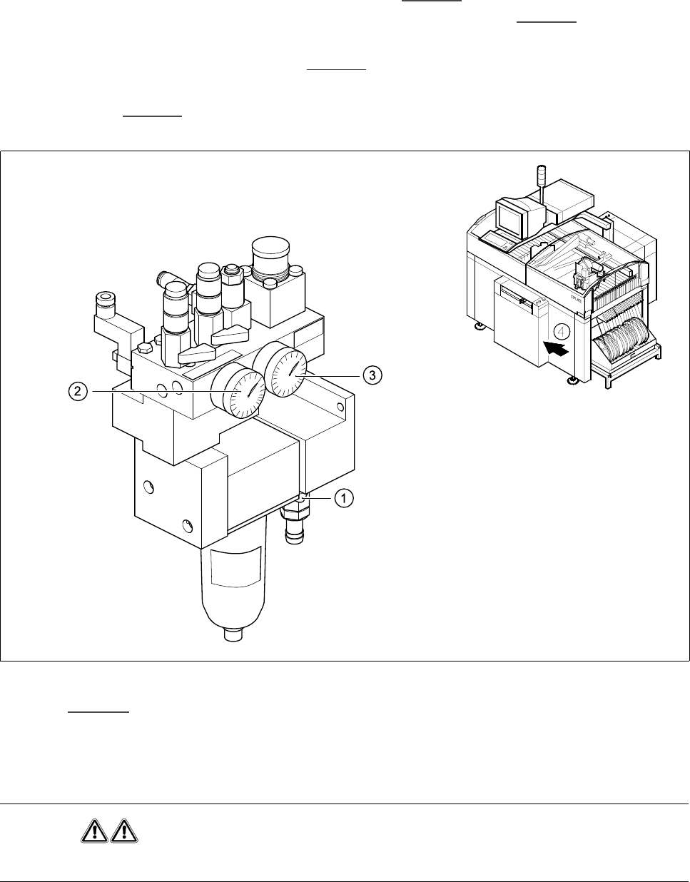
The compressed air working pressure is set to 5,1 bar, although it may fluctuate between 5.0 and 5.3 bar.
The position of the compressed air unit is indicated by item 4 in Fig. 1.4.1
. The compressed air supply to the
automatic placement system can be interrupted using the shut-off valve (item 1 in Fig. 1.4.1
).
- You must remove the cover plate to use the shut-off valve.
- Turn the lever on the shut-off valve (item 1 in Fig. 1.4.1) from the vertical to the horizontal position.
- Watch the working pressure gauge and the pressure gauge for the compressed air supply to the stopper
(item 2 and 3 in Fig. 1.4.1
)
When the automatic placement system is switched on, the pressure discharges to 0 bar within 1 minute.
Fig. 1.4.1 Compressed air unit on the automatic placement system
.H\WR Fig. 1.4.1
1 Shut-off valve lever in the ’CLOSED’ position 2 Working pressure gauge
3 Pressure gauge for the stopper working pressure 4 Position of the compressed air unit on the
placement system
WARNING
NEVER disconnect compressed air lines while they are pressurized. Risk of injury!