80S-20贴片机.pdf - 第322页
9 12-Segment Revolver Head (10000) SIPLACE 80S-20/F4 Service Manual 9.5 Z Axis Unit Edition 07/97 9 - 26
SIPLACE 80S-20/F4 Service Manual 9 12-Segment Revolver Head (10000)
Edition 07/97 9.5 Z Axis Unit
9 - 25
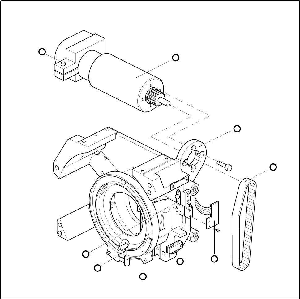
Fig. 9.5.1 Z-axis drive and sensor
1 Motor for z axis
2 Motor mounting
3 Toothed belt for z axis
4 ’Z axis top’ sensor
5 Toothed belt fastening
6 Hexagon socket screw
7 Upper stop for z axis
A Insert z-axis gauge here
5
3
A
7
8
4
1
6
2
9 12-Segment Revolver Head (10000) SIPLACE 80S-20/F4 Service Manual
9.5 Z Axis Unit Edition 07/97
9 - 26

SIPLACE 80S-20/F4 Service Manual 9 12-Segment Revolver Head (10000)
Edition 07/97 9.6 Star Complete
9 - 27
9.6 Star Complete
9.6.1 Removing the ’Star Complete’
PLEASE NOTE
This work may only be carried out by Siemens service technicians or by the customer’s appropriately trained
personnel.
Spare parts
Star, mounted, from item no. 00319775S01
NOTE
When working on the star hold the front part of the head horizontally.
By marking the star and the motor shaft make sure you can refit the star into its original position.
● Remove the front part of the placement head (see section 9.1.6).
● Remove all sleeves.
● Undo the three hexagon socket screws (M3 x 8) in the front part of the star (see Fig. 9.6.1).
● Now lift the complete star assembly until the ball bearings of the segments are exposed.
● Now pull all segments outwards and pull the star completely away.
ATTENTION ∆
!
∆
!
Make sure you not to damage any of the vacuum lines when you remove the star.
9.6.2 Fitting the ’Star Complete’
● Pull all segment guides to the outside.
● Place the star carefully on the motor shaft. Watch out for the three mounting locations.
● Now make sure that no vacuum hoses are jammed between the star and the motor shaft.
● Slide all segment guides back in place. Make sure that all ball bearings of the segments run in the arced
segments guide.
● Press the star lightly onto the motor shaft and fasten it with the three hexagon socket screws (M3 x 8).