80S-20贴片机.pdf - 第327页
SIPLACE 80S-20/F4 Service Manual 9 12-Segment Revolver Head (10000) Edition 07/97 9.6 Star Complete 9 - 31 Fig. 9.6.1 Star complete with drive and forced air unit 1 Star motor 2 Forced a ir un it 3 Front pa rt of th e ho…
9 12-Segment Revolver Head (10000) SIPLACE 80S-20/F4 Service Manual
9.6 Star Complete Edition 07/97
9 - 30
9.6.6 Adjusting the Forced Air Unit
7HVWHTXLSPHQW
– Compressed air testing device, item no. 00313523-01
PLEASE NOTE
The forced air values
that are displayed on the station computer monitor when you select the "Measure forced
air pressure“ option from "Single functions“ or "Test software“ do
QRW
correspond to the air pressures actually
set at the nozzle. They are only used to check that the forced air valve is working correctly.
For this reason, the forced air pressure must
QRW
be set using the values displayed on the monitor. It must
only be set using the compressed air testing device.
The two forced air circuits are activated via a single valve and are thus interdependent.
Nevertheless, various pressures can be set for each circuit using two different flow control valves (see Fig.
9.6.1; points 5 and 6).
6HWWLQJWKH)RUFHG$LU3UHVVXUH9DOXHV8VLQJWKH&RPSUHVVHG$LU7HVWLQJ
'HYLFH
● Load the Sitest program.
● Sitest menu → Head reference run → Close and turn nozzles.
● Sitest menu → Head board → Placement circuit → Switch over forced air.
● Hold the sensor of the compressed air tester against the nozzle (type 714 nozzle recommended) in the
pick-up/placement position.
● Set a value of 0.15 bar for the pick-up/placement circuit (see Fig. 9.6.1; point 5)at the compressed air flow
control.
● Hold the sensor of the compressed air tester against the nozzle in the reject position.
● Set a value of 0.25 bar for the reject circuit (see Fig. 9.6.1; point 6) at the compressed air flow control.
● Repeat the adjustment process several times since the pick-up / placement circuit and the reject circuit are
interdependent.
NOTE
Make sure that the hose of the measurement sensor sits tight on the nozzle.
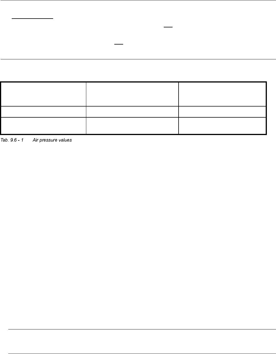
)RUFHGDLUSUHVVXUHYDOXHV
6HWXVLQJWKHFRPSUHVVHGDLUWHVW
LQJGHYLFH
0HDVXUHGDWWKHQR]]OH
'LVSOD\HGRQWKHPRQLWRU
,QSLFNXSSODFHPHQWFLUFXLW
RQO\
Pick-up / placement circuit: 150 mbar (100 – 200 mbar) e.g.: 250 mbar
Reject circuit: 250 mbar (200 – 300 mbar)
There is no sensor
in the reject circuit
SIPLACE 80S-20/F4 Service Manual 9 12-Segment Revolver Head (10000)
Edition 07/97 9.6 Star Complete
9 - 31
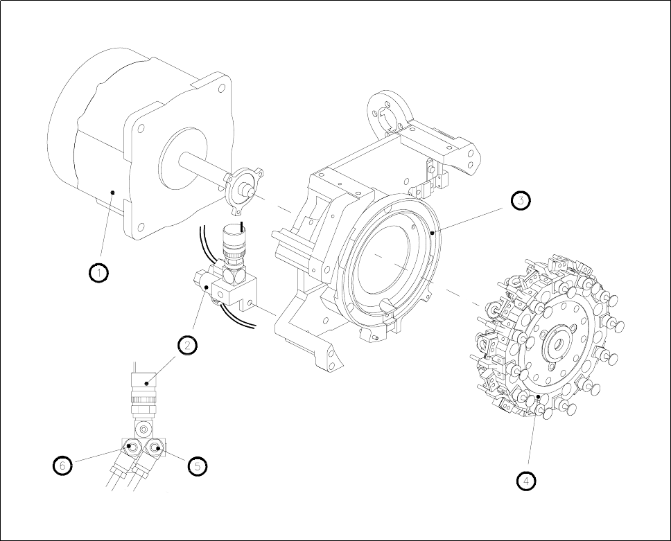
Fig. 9.6.1 Star complete with drive and forced air unit
1 Star motor
2 Forced air unit
3 Front part of the housing
4 Star complete
5 Flow control for pick-up/placement circuit
6 Flow control for reject circuit
9 12-Segment Revolver Head (10000) SIPLACE 80S-20/F4 Service Manual
9.6 Star Complete Edition 07/97
9 - 32