80S-20贴片机.pdf - 第337页
SIPLACE 80S-20/F4 Service Manual 9 12-Segment Revolver Head (10000) Edition 07/97 9.9 12x Nozzle Changer 9 - 41 .H\ WR )LJ 1 Supp ortin g rail 2 Cylind er fixing screws 3 V al ve blo ck fixin g screws 4 No zzle …

9 12-Segment Revolver Head (10000) SIPLACE 80S-20/F4 Service Manual
9.9 12x Nozzle Changer Edition 07/97
9 - 40
6WHSVIRU,QVWDOOLQJWKH0DJD]LQH
● Place the magazine on the associated locating pins (see Fig. 9.9.2, item 3) and the advancing pin (see Fig.
9.9.2, item 2).
● Push down lightly on the magazine until it lies on the support.
● Insert the M3x15 screw and tighten the screw with a hexagon socket-head spanner, size 2.5.
5HSODFLQJWKH1R]]OH&KDQJHU&RQWURO%RDUG
6SDUHSDUWV
– Nozzle changer control board, item no. 00317353-02
7RROV
– Hexagon socket-head spanner, size 2.5
6WHSVIRU5HPRYLQJWKH1R]]OH&KDQJHU&RQWURO%RDUG
● Remove the nozzle changer from the machine as described in section 9.9.1.
● Remove the connecting cable between the 5/2-way valve and plug X2 on the control board.
● Loosen the 4 M3x8 screws (see Fig. 9.9.3, item 9).
● Remove the control board by moving it towards the reject station (see Fig. 9.9.3,
item 11). When you do this, be careful not to damage the actuating plate of the light barrier.
PLEASE NOTE
Do not carry out any work on the actuating plate of the light barrier. This plate is set and coated at the factory.
6WHSVIRU,QVWDOOLQJWKH1R]]OH&KDQJHU&RQWURO%RDUG
● Introduce the control board into the nozzle changer from the reject station side.
● Screw down the board using the 4 M3x8 screws.
● Fit the connecting cable between the 5/2-way valve and plug X2 on the control board.
● Install the nozzle changer in the machine as described in section 9.9.2.
SIPLACE 80S-20/F4 Service Manual 9 12-Segment Revolver Head (10000)
Edition 07/97 9.9 12x Nozzle Changer
9 - 41
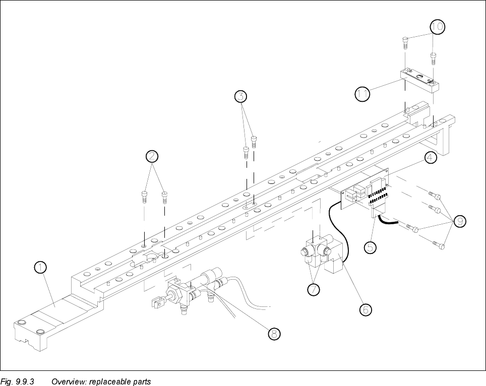
.H\WR)LJ
1 Supporting rail
2 Cylinder fixing screws
3 Valve block fixing screws
4 Nozzle changer control board
5 Control cable plug
65/2-way valve
7 Connections for the cylinder connecting hoses
8 Cylinder
9 Control board fixing screws
10 Reject station fixing screws
11 Complete reject station
9 12-Segment Revolver Head (10000) SIPLACE 80S-20/F4 Service Manual
9.9 12x Nozzle Changer Edition 07/97
9 - 42
5HSODFLQJWKH:D\9DOYH
6SDUHSDUWV
– 5/2-way valve with base plate and cable, item no. 00317578-02
7RROV
– Hexagon socket-head spanners, size 2.5 and 3
6WHSVIRU5HPRYLQJWKH:D\9DOYH
● Remove the nozzle changer from the machine as described in section 9.9.1.
● Remove the connecting cable between the 5/2-way valve and plug X2 on the control board.
● Loosen the screws connecting the compressed air lines to the cylinder (see Fig. 9.9.3, item 7).
● Remove the compressed air hoses from the 5/2-way valve to the cylinder. When you do this, mark which
hose is assigned to which connection.
● Remove the middle magazine of the seven magazines as described in section 9.9.3.1.
● Loosen the 2 M4x16 screws (see Fig. 9.9.3, item 3).
● Remove the 5/2-way valve.
6WHSVIRU,QVWDOOLQJWKH:D\9DOYH
● Insert the 5/2-way valve in the nozzle changer.
● Fix the 5/2-way valve using the 2 M4x16 screws (see Fig. 9.9.3, item 3).
● Connect the compressed air hoses to the cylinder at the associated connections on the 5/2-way valve.
● Tighten the screws of the compressed air connections.
● Fit the connecting cable between the 5/2-way valve and plug X2 on the control board.
● Install the middle magazine of the seven magazines as described in section 9.9.3.2.
● Install the nozzle changer in the machine as described in section 9.9.2