80S-20贴片机.pdf - 第35页
SIPLACE 80S-20/F4/F4-6/F5 Serv ice Manual 1 Operational Safety Edition 04/98 1.5 Energy state of automatic placement systems after switching off at the main switch 1 - 25 (QHUJ\V W DWHRIDXWRPDWLFSODFHPHQWV\ VWHP…
1 Operational Safety SIPLACE 80S-20/F4/F4-6/F5 Service Manual
1.4 Disabling the compressed air supply and discharging the pressure Edition 04/98
1 - 24
SIPLACE 80S-20/F4/F4-6/F5 Service Manual 1 Operational Safety
Edition 04/98 1.5 Energy state of automatic placement systems after switching off at the main switch
1 - 25
(QHUJ\VWDWHRIDXWRPDWLFSODFHPHQWV\VWHPV
DIWHUVZ LWFKLQJRIIDWWKHPDLQVZLWFK
DANGER
Automatic placement systems from the SIPLACE family are powered with 3 x 400 V ± 10 %, 50/60 Hz mains
voltage.
This means that parts of the system carry potentially fatal voltages - even when switched off at the main
switch.
Death, serious injury or considerable damage may result if these placement systems are handled incorrectly.
Always follow the applicable accident prevention and VDE regulations (particularly VDE 0113).
The guards over the control and servo units must ONLY be opened by appropriately qualified and trained per-
sonnel.
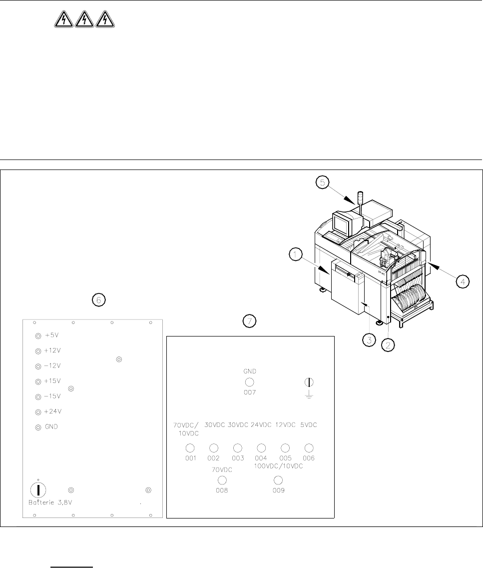
Fig. 1.5.1 Position of the control unit, servo unit, main switch, service socket and compressed air unit on placement systems
.H\WR)LJ
1 Main switch Q1 2 Service socket
3 Compressed air unit 4 Servo unit
5 Control unit 6 Control unit measuring unit
7 Servo unit measuring unit
un-
switched
switched
1 Operational Safety SIPLACE 80S-20/F4/F4-6/F5 Service Manual
1.5 Energy state of automatic placement systems after switching off at the main switch Edition 04/98
1 - 26
1.5.1 Placement system switched off at the main switch, but still con-
nected to the mains
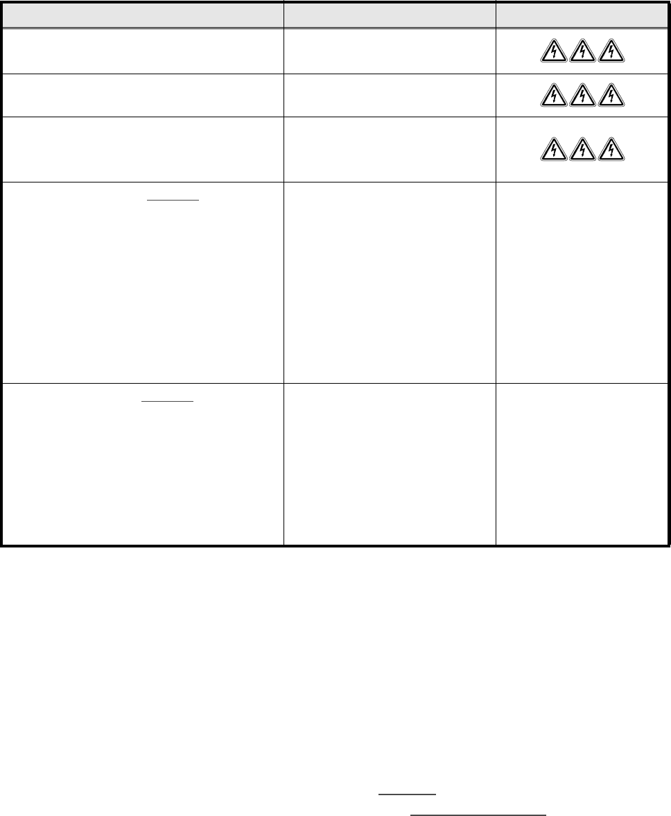
The following table specifies the voltages of assemblies when the automatic placement system is switched off
at the main switch, but still connected to the mains supply.
1.5.2 Placement system switched off at the main switch and discon-
nected from the mains
The automatic placement system is unpowered, apart from slight residual voltages in the servo unit.
1.5.3 Compressed air conditions in the automatic placement system
after switching off at the main switch
When the system is switched off at the main switch (item 1 in Fig. 1.5.1) or if the power supply fails, the elec-
trically-controlled main valve Y1 of the compressed air unit closes (Fig. 1.4.1, page 1 - 23
). The pressure will
drop to 0 bar within 5 seconds.
$VVHPEO\ 9ROWDJH
Mains filter Z1
Terminals L1, L2, L3
3 x 400 VAC
Service socket
230 VAC
Main switch Q1
Terminals 1, 3, 5
Terminals 2, 4, 6
3 x 400 VAC
0 VAC
Servo unit (see item 7 in Fig. 1.5.1)
Test socket 001
Test socket 002
Test socket 003
Test socket 004
Test socket 005
Test socket 006
Test socket 008
Test socket 009
GND 007
< 12 VDC
< 12 VDC
< 12 VDC
0 VDC
0 VDC
0 VDC
< 12 VDC
< 12 VDC
Control unit (see item 6 Fig. 1.5.1)
Test socket 5 V
Test socket + 12 V
Test socket – 12 V
Test socket + 15 V
Test socket – 15 V
Test socket + 24 V
GND
0 VDC
0 VDC
0 VDC
0 VDC
0 VDC
0 VDC
Tab. 1.5 - 1 Voltages of assemblies when the automatic placement system is switched off at the main switch,
but still connected to the main power