80S-20贴片机.pdf - 第360页
12 Vision s ystems SIPLA CE 80S-20/F4/F5 Service Manual 12.2 Replacing the IC vision camera and illumination control board (SIPLACE 80F) E dition 09/99 12 - 8 ● Undo the t wo M3 x 6 h exagon socket screws ( see A in Fig.…

SIPLACE 80S-20/F4/F5 Service Manual 12 Vision systems
Edition 09/99 12.2 Replacing the IC vision camera and illumination control board (SIPLACE 80F)
12 - 7
Key to Fig. 12.1.1
5HSODFLQJWKH,&YLVLRQFDPHUDDQGLOOXPLQDWLRQ
FRQWUROERDUG6,3/$&()
NOTE
Make sure that you always replace the IC vision camera and the illumination control board Y1019 as a pair
since the two components are adjusted to each other. If you fail to do so, you will have problems with compo-
nent centering.
7RROVLQVSHFWLRQPHDVXULQJDQGWHVWHTXLSPHQWUHTXLUHG
6SDUHSDUWV
5HPRYLQJWKH,&YLVLRQFDPHUD
● Remove the component changeover table as described in Section 12.1, page 12 - 5.
1 Connection for communications interface
2 Connection for the power supply to the component changeover table
3 Compressed air connection
4 Holes for the centering pins
5 Hexagon socket screws fastening the components table
6 Area for setting down the component changeover table
7 Horizontal tension jack
8 Centering pins
A Sliding in the lift truck for the changeover table
Set of hexagon socket screwdrivers
SITEST program
'HVLJQDWLRQ )URPLWHPQXPEHU
SIPLACE 80F component vision camera 00306223-04
Current regulator for IC illumination
(board Y1019 included in the camera package)
00323147-02
12 Vision systems SIPLACE 80S-20/F4/F5 Service Manual
12.2 Replacing the IC vision camera and illumination control board (SIPLACE 80F) Edition 09/99
12 - 8
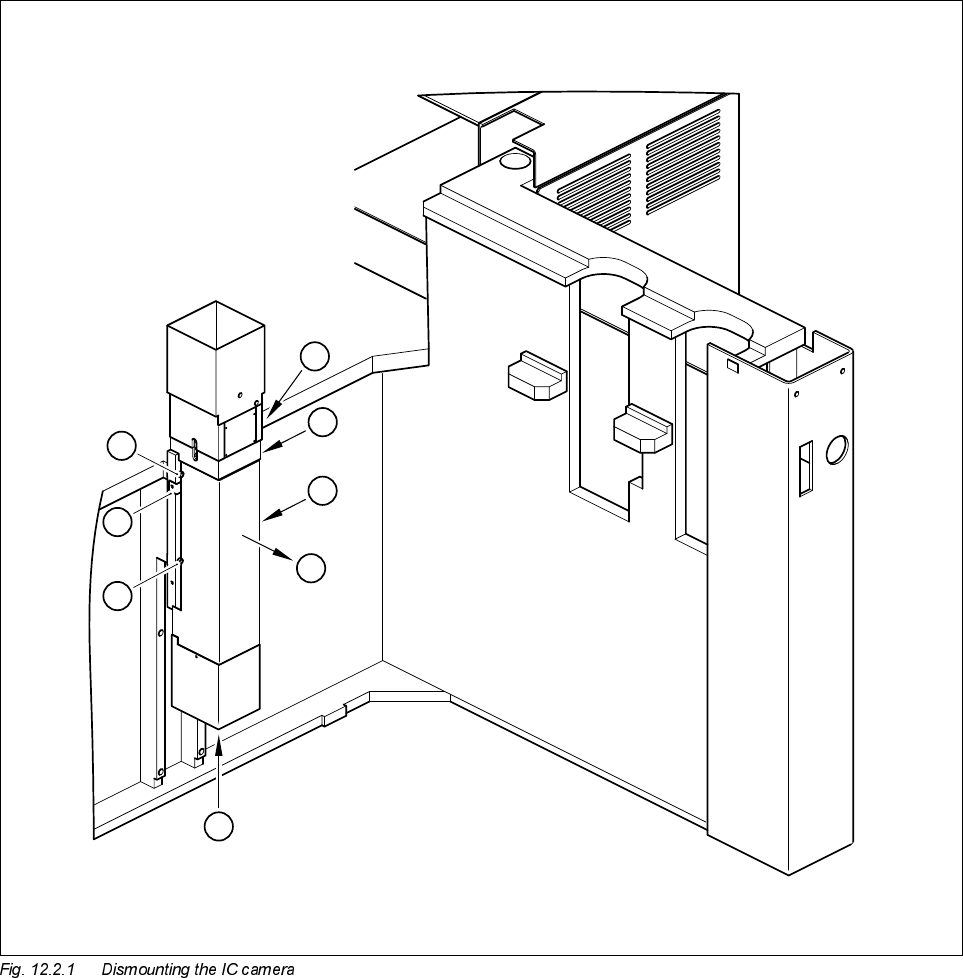
● Undo the two M3 x 6 hexagon socket screws (see A in Fig. 12.2.1) and lift off the cover (see B in Fig.
12.2.1).
● Disconnect cable F0617-W1 from plug X47 of the CCD camera (see C in Fig. 12.2.1).
● Disconnect cable F0616-W1 from plug X1 or from the conversion board ’Y0044 bottom part’ (see C in Fig.
12.2.1).
● Undo the 4 M6 x 20 hexagon socket screws and remove the IC vision camera (see D in Fig. 12.2.1).
D
D
A
B
C
D
D
A

SIPLACE 80S-20/F4/F5 Service Manual 12 Vision systems
Edition 09/99 12.2 Replacing the IC vision camera and illumination control board (SIPLACE 80F)
12 - 9
Key to Fig. 12.2.1
5HPRYLQJWKH,&LOOXPLQDWLRQFRQWUROERDUG<
NOTE
The illumination control board Y1019 is plugged into socket X6 of the ’Motherboard IC illumination Y1018’ in
the terminal panel ’left’ (D0904).
● Disconnect cable F0616-W1 from plug X2kk of the IC illumination control board (see ➁ in Fig. 12.2.2).
● Remove the illumination control board Y1019 from the ’Motherboard IC illumination Y1018’.
)LWWLQJWKH,&YLVLRQFDPHUDDQGLOOXPLQDWLRQFRQWUROOHU
● When fitting, proceed in the reverse sequence of actions as described in Section 12.2.3, page 12 - 7 and
Section 12.2.4, page 12 - 9.
● Make sure that the board and plugs are seated properly.
● Be careful not to pinch or squash the cables.
6HWWLQJZRUN
● Calibrate the IC vision camera with the aid of the SITEST program.
● Once you have completed your setting work, fit the component changeover table back again.
A Undo and remove the screws for the cover
B Remove the cover
C Unplug the plugs from the IC camera and the conversion board
D Undo the mounting screws