80S-20贴片机.pdf - 第361页
SIPLACE 80S -20/F4/F5 S ervice Man ual 12 Vision systems Edition 09/99 12.2 Replacing the I C vision camera and illumination control board (SIPLACE 80F) 12 - 9 Key to Fig. 12.2.1 5 HPRY LQJWKH ,&LO OXPL QD…
12 Vision systems SIPLACE 80S-20/F4/F5 Service Manual
12.2 Replacing the IC vision camera and illumination control board (SIPLACE 80F) Edition 09/99
12 - 8
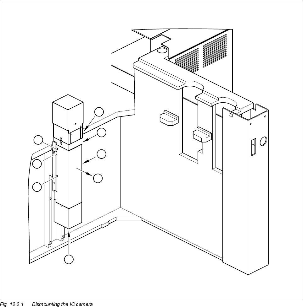
● Undo the two M3 x 6 hexagon socket screws (see A in Fig. 12.2.1) and lift off the cover (see B in Fig.
12.2.1).
● Disconnect cable F0617-W1 from plug X47 of the CCD camera (see C in Fig. 12.2.1).
● Disconnect cable F0616-W1 from plug X1 or from the conversion board ’Y0044 bottom part’ (see C in Fig.
12.2.1).
● Undo the 4 M6 x 20 hexagon socket screws and remove the IC vision camera (see D in Fig. 12.2.1).
D
D
A
B
C
D
D
A

SIPLACE 80S-20/F4/F5 Service Manual 12 Vision systems
Edition 09/99 12.2 Replacing the IC vision camera and illumination control board (SIPLACE 80F)
12 - 9
Key to Fig. 12.2.1
5HPRYLQJWKH,&LOOXPLQDWLRQFRQWUROERDUG<
NOTE
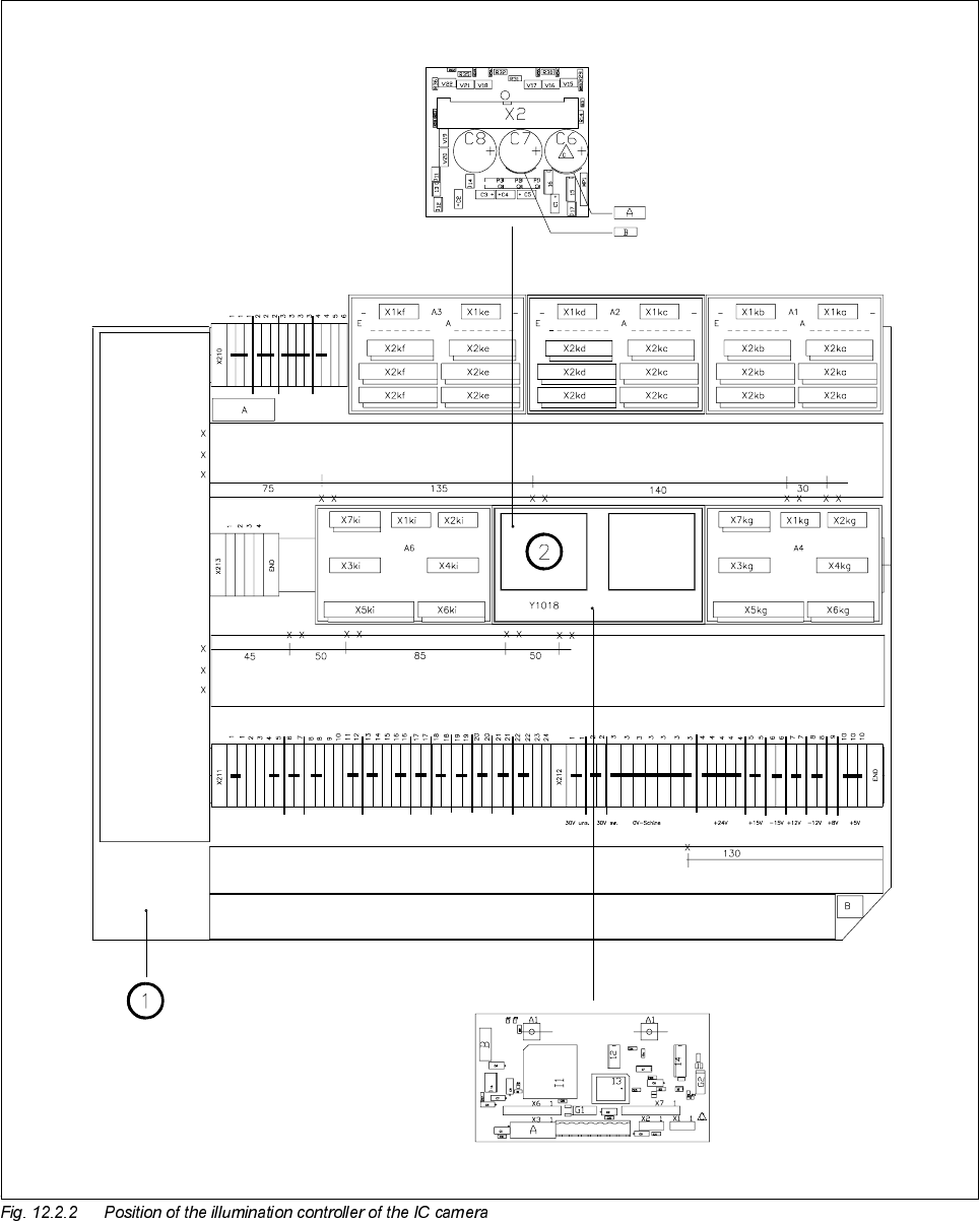
The illumination control board Y1019 is plugged into socket X6 of the ’Motherboard IC illumination Y1018’ in
the terminal panel ’left’ (D0904).
● Disconnect cable F0616-W1 from plug X2kk of the IC illumination control board (see ➁ in Fig. 12.2.2).
● Remove the illumination control board Y1019 from the ’Motherboard IC illumination Y1018’.
)LWWLQJWKH,&YLVLRQFDPHUDDQGLOOXPLQDWLRQFRQWUROOHU
● When fitting, proceed in the reverse sequence of actions as described in Section 12.2.3, page 12 - 7 and
Section 12.2.4, page 12 - 9.
● Make sure that the board and plugs are seated properly.
● Be careful not to pinch or squash the cables.
6HWWLQJZRUN
● Calibrate the IC vision camera with the aid of the SITEST program.
● Once you have completed your setting work, fit the component changeover table back again.
A Undo and remove the screws for the cover
B Remove the cover
C Unplug the plugs from the IC camera and the conversion board
D Undo the mounting screws