80S-20贴片机.pdf - 第365页
SIPLACE 80S -20/F4/F5 S ervice Man ual 12 Vision systems Edition 09/99 12.3 Replacing the flip-chip vision camera and illumination controller (SIPLACE 80F) 12 - 13 5HPRY LQJWKH IOLSFKLSLO OXPLQD WLRQF RQWURO…

SIPLACE 80S-20/F4/F5 Service Manual 12 Vision systems
Edition 09/99 12.3 Replacing the flip-chip vision camera and illumination controller (SIPLACE 80F)
12 - 13
5HPRYLQJWKHIOLSFKLSLOOXPLQDWLRQFRQWUROERDUG<
NOTE
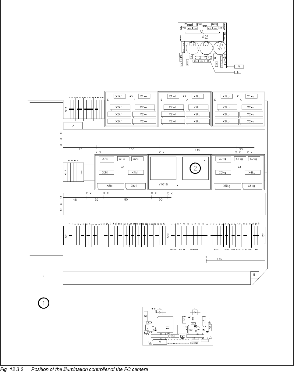
The illumination control board Y1019 is plugged into socket X7 of the ’Motherboard IC illumination Y1018’ in
the terminal panel ’left’ (D0904).
● Disconnect cable F0616-W2 from plug X2kk of the FC illumination control board
(see
➁
in Fig. 12.3.2 page 12 - 14).
● Remove the illumination control board Y1019 from the ’Motherboard IC illumination Y1018’.
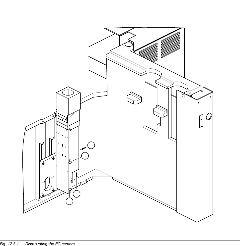
)LWWLQJWKHIOLSFKLSYLVLRQFDPHUDDQGLOOXPLQDWLRQFRQWUROOHU
● When fitting, proceed in the reverse sequence of actions as described in Section 12.3.3, page 12 - 11 and
Section 12.3.4, page 12 - 13.
● Make sure that the board and plugs are seated properly.
● Be careful not to pinch or squash the cables during installation.
6HWWLQJZRUN
● Calibrate the flip-chip vision camera with the aid of the SITEST program.
● Once you have completed your setting work, fit the component changeover table back again.