80S-20贴片机.pdf - 第385页
SIPLACE 80S -20/F4/F5 S ervice Man ual 12 Vision systems Edition 09/99 12.6 Coplanarity Option 12 - 33 Key to Fig. 12 .6.8 (look to your left): 1) Coplana rity sens or (laser) 2) Sensor bracke t 3) Optio nal car rier for…
12 Vision systems SIPLACE 80S-20/F4/F5 Service Manual
12.6 Coplanarity Option Edition 09/99
12 - 32
● Keeping the above DANGER text in mind, dismantle the empty-tape duct and the cutter (old model) or the
“pneumatic cutter”.
Proceed exactly as described in the pertinent SIPLACE Service Manual, under “Exchanging the
Cutter...".
-> Note in the case of the pneumatic cutter that the retaining bracket remains mounted.
● Continue the work by dismantling the sensor bracket (see Section 12.6.7) or the sensor cable (see Sec-
tion 12.6.8).
([FKDQJLQJWKH6HQVRU%UDFNHW

SIPLACE 80S-20/F4/F5 Service Manual 12 Vision systems
Edition 09/99 12.6 Coplanarity Option
12 - 33
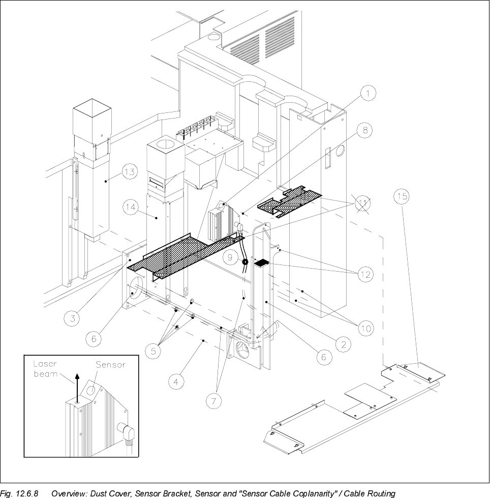
Key to Fig. 12.6.8 (look to your left):
1) Coplanarity sensor (laser) 2) Sensor bracket
3) Optional carrier for nozzle changer / flip-chip camera 4) Fasteners for sensor bracket
/ coplanarity sensor (remains mounted) Four M 6 x 20 socket-head cap screw
5) 8 ea. spacers 1 mm thick (2 spacers/screw) 6) Opening to run lines for coplanarity sensor
(only in case of dual conveyor, stationary side left and flip-chip camera
or right, inserted between bracket and optional carrier)
7) "Sensor cable coplanarity" 8) Fasteners for the sensor (laser)
three M 4 x 8 socket-head cap screws
9) 2 cable clips D = 6 mm 10) Fasteners for cable clips
two washers 4.3 DIN 125-A
two M 4 x 8 socket-head cap screws
11) Plastic dust cover *) over the conveyor trench 12) Contact surfaces for dust cover
Pos. 15 is always substituted
(see NOTE, below)
13) IC camera (remains mounted) 14) Flip-chip camera (remains mounted)
15) Metal dust cover
Fasteners: 3 or 4 ea washers 4,3 DIN 9021-A
3 or 4 ea M4 x 10 socket-head cap screws
NOTE in re *)
If a plastic dust cover is still installed (earlier model), this must be replaced by the metal dust cover (see Sec-
tion 12.6.10).
12.6.7.1 Disassembly: Sensor Bracket
● Precondition: The "Preparatory Steps" (Section 12.6.6) must be completely finished.
CAUTION O
During the following steps, make certain that you do not damage the cable (bracket has sharp corners) or
place any strain on the cables.
● Undo the fasteners holding the dust cover on the machine base under the PCB conveyor module (three or
four washers and M4 socket-hex cap screws) and remove the dust cover.
● If a metal cover is over the flip-chip camera, removed it so that you can unplug the cables.
● Unplug the ribbon cable (illumination control) and the video lead from the flip-chip camera (see Fig.
12.6.8).
● Carefully loosen any cable ties along the ribbon cable.
● Undo the screws fastening the sensor cable to the sensor bracket (2 cable clips, 2 washers, 2 M4 socket
hex cap screws: see Fig. 12.6.8 -> 10).

12 Vision systems SIPLACE 80S-20/F4/F5 Service Manual
12.6 Coplanarity Option Edition 09/99
12 - 34
● Unplug the connector of the "sensor cable coplanarity" on the sensor.
● Thread the "sensor cable coplanarity", the ribbon cable (illumination control) and the video cable in
through the hole in the sensor bracket (see Fig. 12.6.8 -> 2 and 6) and then out.
● Undo the screws fastening the coplanarity sensor to the sensor bracket
(three M4 x 3 socket-hex cap screws: (see Fig. 12.6.8 -> Pos. 8) and carefully put the sensor aside.
-> At least one of the 3 screws may be secured with Loctite but it must be loosened anyway.
NOTE:
If a dual conveyor is installed (stationary side on left or right) 2 spacer washers
HDFKRI
mm thick
must be placed under each screw fastening the sensor bracket. Make certain that these washers are not
lost when the bracket is dismantled.
● Undo the screws fastening the sensor bracket to the optional carrier (four M6 x 20 screws: see Fig. 12.6.8
-> 4) and remove the sensor bracket any any spacer washers under the screws.
12.6.7.2 Installation: Sensor Bracket
CAUTION O
While assembling the sensor bracket, secure the IC camera´s ribbon cable to prevent it from being
damaged.
During the following steps, be careful not to damage the cables (bracket has sharp corners) or exert any strain
on the cables.
● From inside of the sensor bracket, carefully thread the "sensor cable coplanarity", the ribbon cable (illu-
mination control) and the video cable from inside of the sensor bracket out through the hole in the side of
the sensor bracket to the right (see Fig. 12.6.8 -> 2 and 6).
● Fasten the coplanarity sensor to the new sensor bracket.
(three M 4 x 8 socket-hex cap screws: see Fig. 12.6.8 -> Pos. 8).
Do not fully tighten the screws yet: the sensor hasn’t been leveled (see below).
NOTE:
Fastening the sensor cable as follows ensures that the dust cover cannot cause damage to the cable.
● Connect the plug-in connector of the sensor cable to the sensor.
● Fasten the sensor cable to the side facing the IC camera to the sensor bracket (see Fig. 12.6.8 -> 9 and
10), 2 washers, two M4 x 8 socket-hex cap screws).