80S-20贴片机.pdf - 第397页
SIPLACE 80S -20/F4/F5 S ervice Man ual 12 Vision systems Edition 09/99 12.6 Coplanarity Option 12 - 45 ● If de sired, a ctuate the “Displa y” button to see the meas ured values . ● Termin ate the menu “COPLANA RITY”. ● T…

12 Vision systems SIPLACE 80S-20/F4/F5 Service Manual
12.6 Coplanarity Option Edition 09/99
12 - 44
12.6.16.1Preconditions
● Aside from coplanarity, the machine is completely calibrated.
12.6.16.2 V 403.04: Performing Calibration
● Procedure: As described below for Version > 404.01 with the following difference:
12.6.16.3 > V 404.01: Performing Calibration
● Turn the machine on and start the SITEST program.
● Carry out the “total reference run” in the SITEST program.
● Pick up nozzle no. 417 with the IC head.
● Select the function menu “IC HEAD” -> “COPLANARITY”.
The display of the initial positions of the new coplanarity sensor follows (configuration data)
X = 444000 Y = 595000 Z = 17000
● Select the function menu -> “CALIBRATE MODULE”
● When the request appears on the screen, place the coplanarity calibration tool in the middle of the cal-
ibration tool pocket on the stationary side of the conveyor.
● Close the protective hoods and actuate the “Start” button.
● The calibration starts automatically. The calibration values determined are displayed.
Possible error messages during this process:
- X-Y- position not located.
Possible causes:
- Position of coplanarity sensor is wrong because:
- In case of 404.01: Wrong, i.e., old coplanarity module ("LCM150") - and thus the old
X-, Y- (and Z) -position - were entered.
- In the case of machines with dual conveyors (left-hand or right-hand conveyor side = stationary):
spacer washer (total 2 mm thick) between the sensor bracket and the optional carrier or nozzle
changer were not installed or more/less than two washers (1mm each) were installed
(see Fig. 12.6.8 -> 5).
- In case of machines with a single conveyor: Spacer washers were installed at the
above location ( = incorrect).
- Focus outside of tolerances
Possible causes:
- Calibration tool damaged or not picked up.
- Diameter of calibration tool not within tolerances
Possible cause:
- Nozzle projects over calibration tool -> Wrong nozzle picked up (= not 417).
SIPLACE 80S-20/F4/F5 Service Manual 12 Vision systems
Edition 09/99 12.6 Coplanarity Option
12 - 45
● If desired, actuate the “Display” button to see the measured values.
● Terminate the menu “COPLANARITY”.
● Terminate the SITEST program.
● Answer “YES” to the question being displayed: “Store the data?”
The offset values for X, Y and Z are entered in the real.ma data under coplanarity_2_x /.... _y /.... _z .
● Press EMERGENCY OFF and remove the calibration tool.
● As the final step, check whether the IC camera and flip-chip camera function.
,Q&DVHRI3UREOHPVRU(UURUV
12 Vision systems SIPLACE 80S-20/F4/F5 Service Manual
12.6 Coplanarity Option Edition 09/99
12 - 46
&KHFN3RVLWLRQRI&RSODQDULW\6HQVRU!9[[
12.6.17.1Overview
NOTE
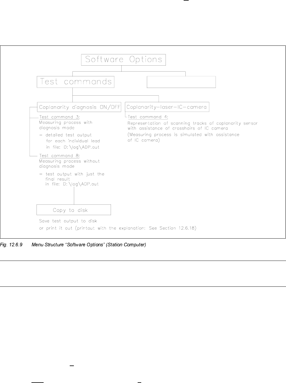
For the execution of test commands 3 and 8 see Section 12.6.18, Run Data Protocol (German: ADP).
You can utilize test command 4 (see Fig. 12.6.9) to check whether the laser track strikes the leads.
- The component to be measured is optically centered after test command 4 is called up. Instead of being
moved over the coplanarity sensor, it is moved over the camera., i.e., the measurement process is there-
fore simulated.
- The midpoint of the IC camera (crosshairs) corresponds to the focus point of the coplanarity sensor.
12.6.17.2Procedure (> V 403.xx)
● Execute only in case of software version 403.04 -> D:\DAT\SST.MA, speed factor:
If this value is > 200 reduce the value to 200 (= higher accuracy).