80S-20贴片机.pdf - 第420页
13 6-Segment Revolver Head (8000) SIPLACE 80S-20/F4 Service Manual 13.1 6-Segment Revolver Head (8000) Edition 07/97 13 - 6 Fig. 13.1.2 M ounting and dismantli ng the cover 13.1.6 Removing the ’Placeme nt Head Complete’ …
SIPLACE 80S-20/F4 Service Manual 13 6-Segment Revolver Head (8000)
Edition 07/97 13.1 6-Segment Revolver Head (8000)
13 - 5
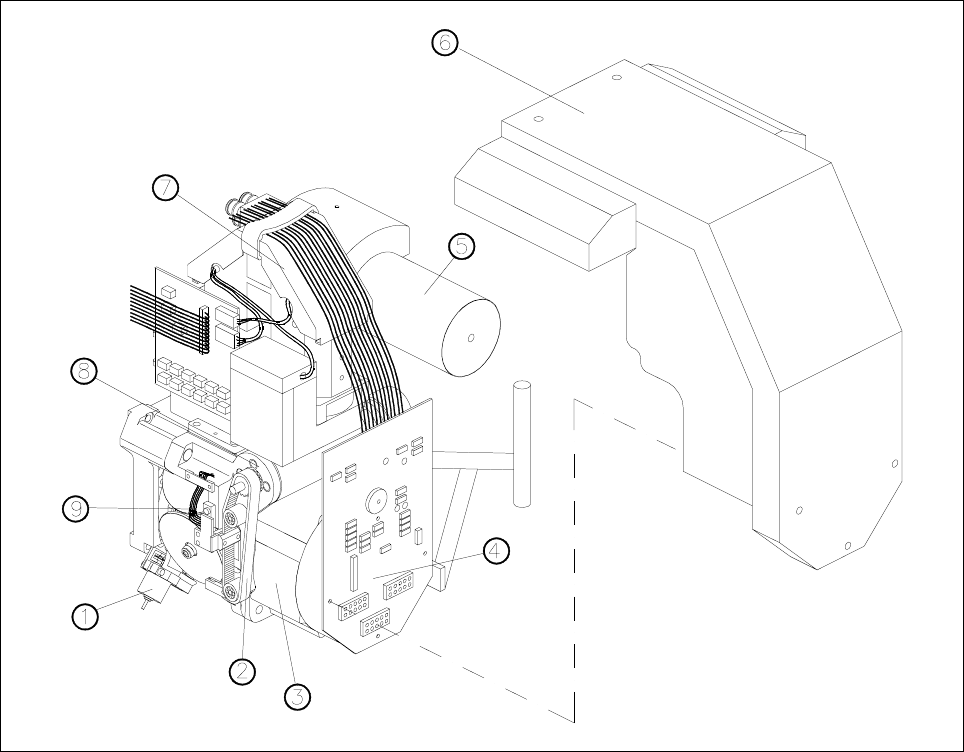
13.1.4 Structure of the 6-Segment Revolver Head (8000)
Fig. 13.1.1 Structure of the 6-segment revolver head 8000
1 Reject circuit valve adjustment drive
2 Z axis toothed belt
3 Star motor
4 Distributor board
5Silencer
6 Head cover
7 Components camera
8 Z motor
9Star
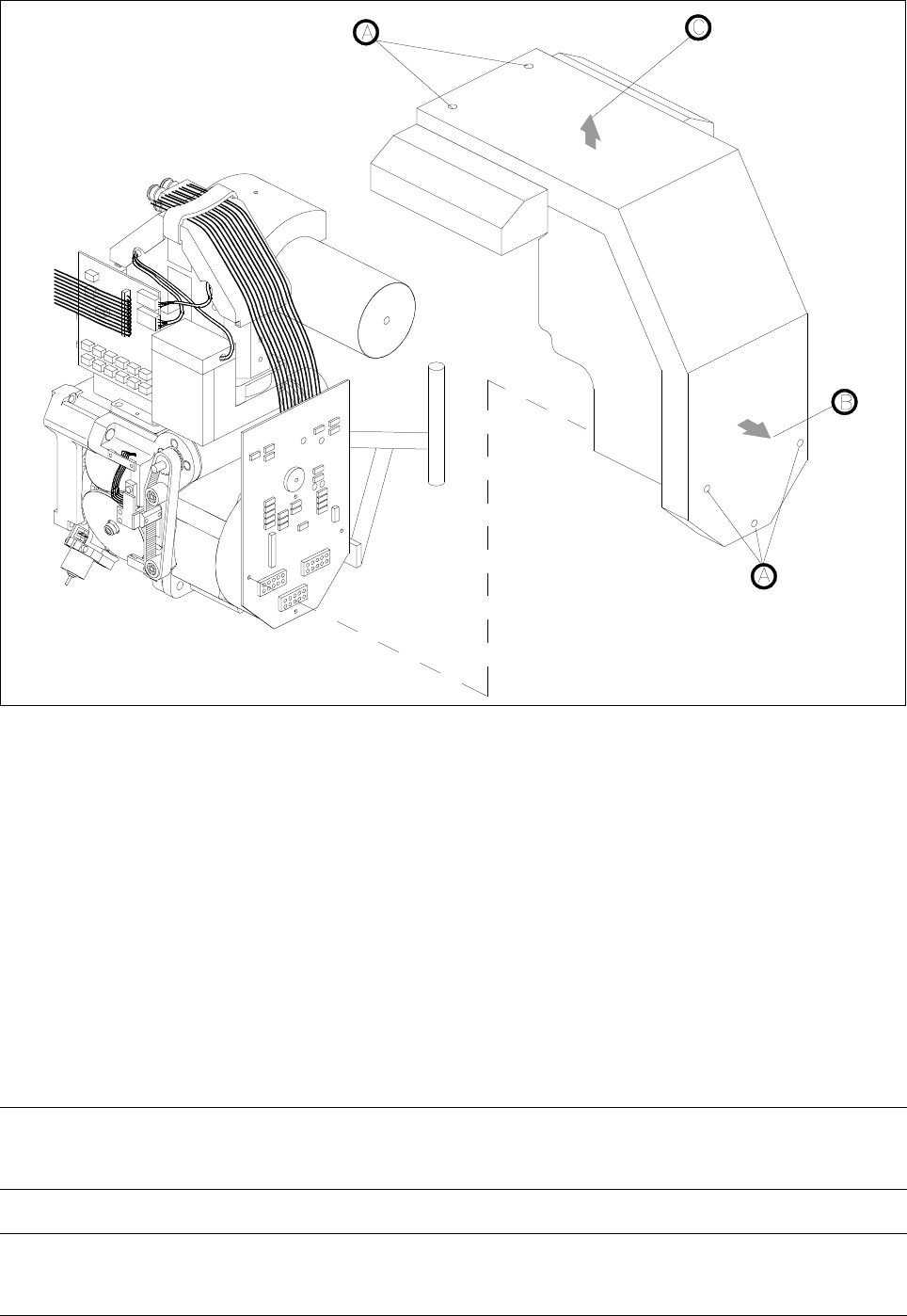
13.1.5 Removing the ’Cover complete’
● Remove the five M3x5 hexagon socket screws for mounting the cover (see Fig. 13.1.2, point A).
● Pull the cover a little towards you in horizontal direction (see Fig. 13.1.2, point B).
● Lift the cover up and away (see Fig. 13.1.2,point C).
● To install the cover, proceed in the reverse sequence of operations.
13 6-Segment Revolver Head (8000) SIPLACE 80S-20/F4 Service Manual
13.1 6-Segment Revolver Head (8000) Edition 07/97
13 - 6
Fig. 13.1.2 Mounting and dismantling the cover
13.1.6 Removing the ’Placement Head Complete’
Spare parts
Revolver head 8000, from item no. 00324963S01
● Disconnect plug-in connections X3, X10, X12, X13, X14, X17, X18 and X19 from head board C0005.
● Disconnect all compressed air lines from the back of the vacuum generator.
● Undo the three hexagon socket screws (M4 x 16) (Refer to section 13.1.3 A) and carefully remove the
placement head from the placement machine.
– To install the head, proceed in the reverse sequence of operations.
NOTE
Pay attention to the keying of the plug when you reconnect the plug-in connections to head board C0005.
CAUTION ∆
!
Make sure you do not damage the cable or put tensile stress on the snap-in connections.
SIPLACE 80S-20/F4 Service Manual 13 6-Segment Revolver Head (8000)
Edition 07/97 13.1 6-Segment Revolver Head (8000)
13 - 7
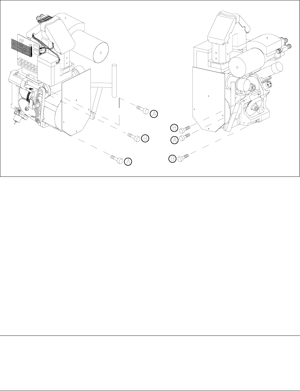
Fig. 13.1.3 Fastening screws of the 8000 placement head and the front part of the placement head
Key to Fig. 13.1.3
A Fastening screws of the placement head, complete
B Fastening screws for the front part of the placement head
13.1.7 Removing the Front Part of the Placement Head
● Disconnect plug-in connections X3, X10, X12, X13 and X14 from head board C0005.
● Disconnect the compressed air line for the forced air unit from the front of the vacuum generator.
● Undo the three hexagon socket screws (M4 x 16) (Refer to section 13.1.3 B) and remove the front part of
the placement head from the placement machine.
● To re-install the front part of the head, proceed in the reverse sequence of operations.
● For information on the components camera adjustment procedure, please refer to the Sitest instructions.
NOTE
When you remove or re-install the front part of the placement head note that the star is rotated by 15° out of its
zero position (vertical sleeve position).
When you fit the front part of the placement head, make sure that the distributor disc (see Pos. 3, Fig. 13.4.2,
page 13 - 18) is positioned correctly.