80S-20贴片机.pdf - 第423页
SIPLACE 80S-20/F4 Service Manual 13 6-Segment Revolver Head (8000) Edition 07/97 13.2 R eplacing the Valve Adjustment Dr ive for the Placement or Reject Circuits 13 - 9 Fig. 13.2.1 Adjustment work on the valve adjustment…

13 6-Segment Revolver Head (8000) SIPLACE 80S-20/F4 Service Manual
13.2 Replacing the Valve Adjustment Drive for the Placement or Reject Circuits Edition 07/97
13 - 8
13.2 Replacing the Valve Adjustment Drive for the
Placement or Reject Circuits
13.2.1 Replacing the Valve Adjustment Drive of the Placement Circuit
Spare parts
– Valve adjustment drive, from item no. 00319825S02
Test equipment
– Distance gauge, from item no. 00325445-01
● Remove the complete placement head (see section 13.1.6).
● Undo the two recessed-head screws (M2 x 6) of the ribbon cable holders.
● Undo the hexagon socket screw (M3 x 10) and carefully pull away the valve adjustment drive (see Fig.
13.2.2).
● To re-install the placement head, proceed in the reverse sequence of operations.
NOTE
When fitting the head, check the position of the two locating pins. (There is play between the pins and the
holes).
When you re-install the ribbon cable holders, make sure that you do not pinch the cables.
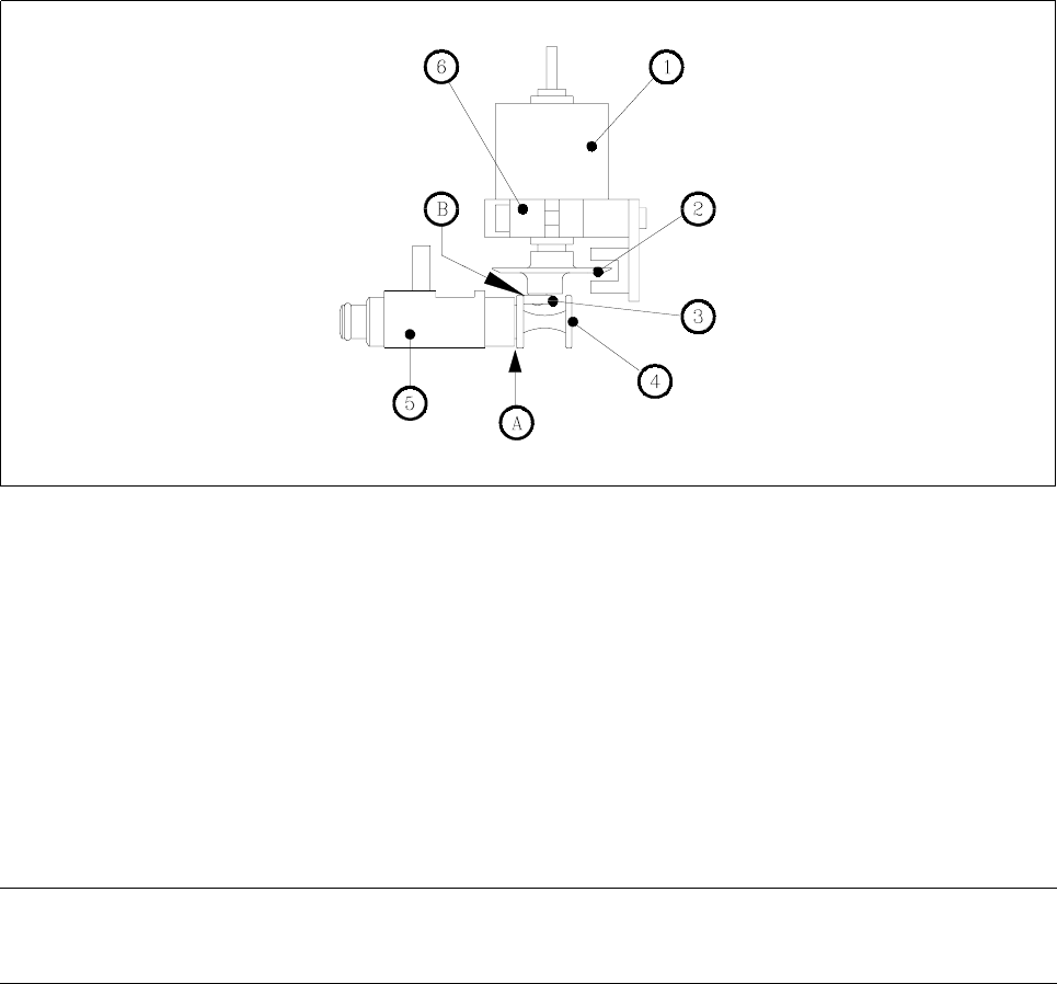
Adjustment Work
– Using the distance gauge adjust the distance between the plunger head and the valve housing to 0.2mm
(point A).
– Turn the adjustment disc ➁ and move the adjustment unit ➅, that the deep-groove ball bearing ➂ will touch
the plunger head (point B).
– Fix the adjustment unit with the screws.
SIPLACE 80S-20/F4 Service Manual 13 6-Segment Revolver Head (8000)
Edition 07/97 13.2 Replacing the Valve Adjustment Drive for the Placement or Reject Circuits
13 - 9
Fig. 13.2.1 Adjustment work on the valve adjustment unit
Key to Fig. 13.2.1
1 Step motor
2 Adjustment disc
3 Deep-groove ball bearing
4 Plunger
5 Valve housing
6 Adjustment unit
A Adjust distance between plunger and valve housing to 0.2mm using the distance gauge.
B The deep-groove ball bearing has to touch the plunger head.
NOTE
If placement is slightly offset you will need to readjust the placement head (see the Sitest instructions).

13 6-Segment Revolver Head (8000) SIPLACE 80S-20/F4 Service Manual
13.2 Replacing the Valve Adjustment Drive for the Placement or Reject Circuits Edition 07/97
13 - 10
13.2.2 Replacing the Valve Adjustment Drive for the Reject Circuit
Spare parts
Valve adjustment drive, from item no. 00319825S02
Test equipment
Distance gauge, from item no. 00325445-01
● Remove the complete placement head (see section 13.1.6).
● Undo the two recessed-head screws (M2 x 6) of the ribbon cable holders.
● Undo the hexagon socket screws (M3 x 10) and carefully pull away the valve adjustment drive (see Fig.
13.2.2).
● To re-install the valve adjustment drive, proceed in the reverse sequence of operations.
NOTE
When fitting the head, pay attention to the position of the two alignment pins.
When you re-install the ribbon cable holders make sure that you do not pinch the cables.
Adjustment Work
Carry out the adjustment work as described in section 13.2.1, page 13 - 8.
– If placement is slightly offset you will need to readjust the placement head (see the Sitest instructions).