80S-20贴片机.pdf - 第472页
Service Manual SIPLACE 80S-2 0/F4/F5 14 Pneumatic Cut ter Edition 04/98 14.1 Pneumatic Cutter and Empty-Tape Duct 14 - 14 Fig. 14.1.7 Removing and Installing the Short-Stroke Cylinder .H\ 1) Short- stroke c ylinders 1 …

14 Pneumatic Cutter Service Manual SIPLACE 80S-20/F4/F5
14.1 Pneumatic Cutter and Empty-Tape Duct Edition 04/98
14 - 13
HINWEIS
Note the mounting positions of the blades (see Fig. 14.1.6).
The deflector plate on the rail of the movable blade (see Fig. 14.1.6 -> 7) must face the stationary blade (see
Fig. 14.1.6 -> 2).
● ,QVWDOOWKHEODGHVLQFOXGLQJUDLOFRUUHFWO\DQGDVVHPEOHWKHFXWWHU
as described in Section 14.1.7.2.
● Perform the appropriate “Final Steps” (see Section 14.1.17).
14.1.9 Exchanging the Short-Stroke Cylinder Left / Right
The cutter remains installed in the machine.
DANGER O O O
6WULFWO\
adhere to the instructions in the DANGER text in Section 14.1.1.
● Perform all steps up to and including “..loosening the bolts fastening the articulated joint” (in this case only
on the faulty short-stroke cylinder) as described in Section 14.1.7.
-> The movable blade is left
LQVWDOOHG
.
● Mark the mounting position of the disassembled stationary blade (including the rail), e.g., with the water-
insoluble marker:
-> This mounting position ( = right-hand end remains on the right) must be restored during installation.
● Undo the compressed air connections on the faulty short-stroke cylinder (see Fig. 14.1.7 -> 8).
● Loosen the fastening bolts of the two inductive proximity switches on the short-stroke cylinder (one bolt
each: see Fig. 14.1.7 -> 4, 5) and mark the allocation of the proximity switches (position at front/back).
● Loosen bolts fastening the faulty short-stroke cylinder (2 bolts: see Fig. 14.1.7 -> 2) and remove the cylin-
der including the articulated joint which was screwed in.
Service Manual SIPLACE 80S-20/F4/F5 14 Pneumatic Cutter
Edition 04/98 14.1 Pneumatic Cutter and Empty-Tape Duct
14 - 14
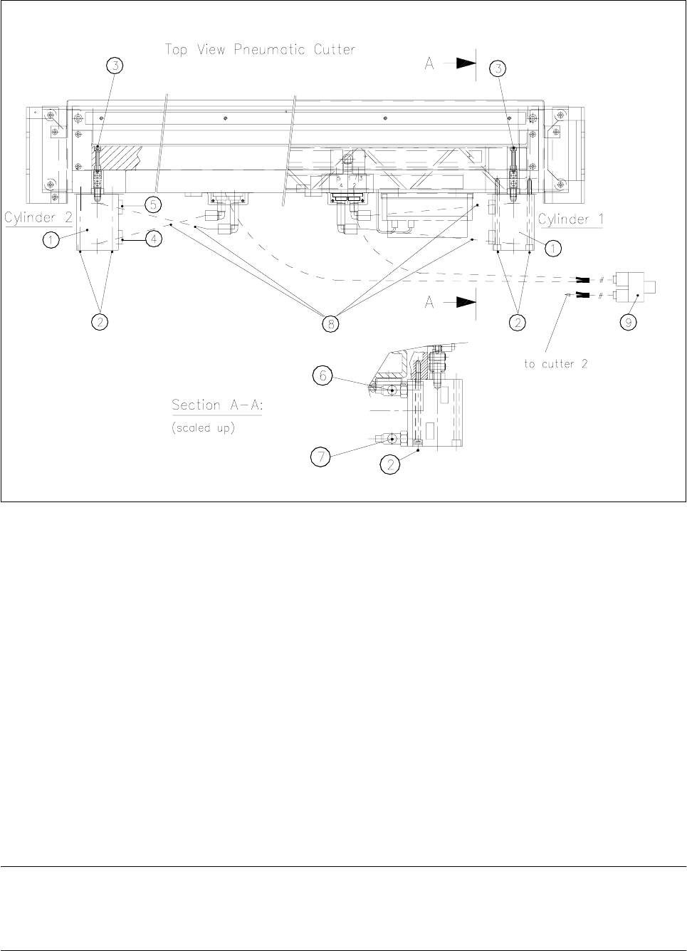
Fig. 14.1.7 Removing and Installing the Short-Stroke Cylinder
.H\
1) Short-stroke cylinders 1 and 2 2) Fastening the short-stroke cylinders
2 socket hex bolts each, M5 x 75
3) Fastening the articulated joint (see also Fig. 14.1.5) 4) Proximity switch (run
LQ
for cylinder)
Fastening: 1 cross-slotted bolt
5) Proximity switch (run
RXW
for position) 6) One-way restrictor (run
RXW
for cylinder)
Fastening: 1 cross-slotted bolt
7) Drosselrückschlagventil (für Zylinder einfahren)
8) Allocation of the compressed air connections, 9) Y-socket union (compressed air 5 bar compressed
air hoses from safety valve)
● Dismantle articulated joint from the cylinder by turning the open-end wrench (width across flats 10) on the
surface indicated in Fig. 14.1.8 -> 3.
NOTE
The threaded pin is secured with Loctite no. 243, so it takes somewhat more strength to loosen it. If neces-
sary, warm the area where it is screwed in until the articulated joint can be loosened.
14 Pneumatic Cutter Service Manual SIPLACE 80S-20/F4/F5
14.1 Pneumatic Cutter and Empty-Tape Duct Edition 04/98
14 - 15
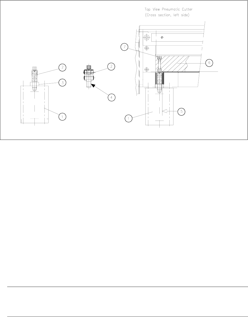
Fig. 14.1.8 Removing Articulated joint from the Cylinder, Installing It on New Master Cylinder and Bonding It in Place
Key:
1) Short-stroke cylinder (1 or 2) 2) Articulated joint (complete)
3) Wrench surface for disassembling the 4) Secure articulated joint thread with Loctite no. 243
articulated joint
5) Open-end wrench surface of articulated joint 6) Friction surface of the movable blad
7) Fastening the articulated joint (see also Fig. 14.1.5)
● Clean the residues of Loctite from thread of articulated joint pin and apply a small amount of Loctite no.
243 (item no.: see Section 14.1.3) to the thread.
● Screw the threaded pin into the new short-stroke cylinder (item no.: see Section 14.1.2).
Turn the articulated joint into the mounting position (see Fig. 14.1.8, diagram on left) and tighten the
articulated joint against the wrench surface.
● Disassemble the one-way restrictors from the faulty cylinder and screw them in correctly allocated for
“move in/move out” on the new cylinder (open-end wrench, size 14).
-> Afterwards, check and, if necessary, correct the setting of the one-way restrictors.
● Remount the prepared cylinder on the cutter (2 bolts: see Fig. 14.1.7).
HINWEIS
Make certain that the lateral surface / open-end wrench surface of the articulated joint (see Fig. 14.1.8
-> 5) is DWULJKWDQJOHWRWKHIULFWLRQVXUIDFHof the movable wrench ( -> 6).
● Fasten the cylinder in this position with the 2 bolts each (see Fig. 14.1.7 -> 2).
● Remount the 2 proximity switches in the FRUUHFWDOORFDWLRQ(position: front/back on the cylinder (see Fig.
14.1.7 -> 4, 5).
-> As the final step, the switching points must be adjusted (see Section 14.1.13).