80S-20贴片机.pdf - 第475页
14 Pneumatic Cutter Service Manual SIPLACE 80S- 20/F4/F5 14.1 Pneumatic Cutter and Empty-Tape Duct Edition 04/98 14 - 17 ● IIf the hose is okay, ma ke su re the sh ort-st roke cylind er is no t slug gish. If th ere i s, …

Service Manual SIPLACE 80S-20/F4/F5 14 Pneumatic Cutter
Edition 04/98 14.1 Pneumatic Cutter and Empty-Tape Duct
14 - 16
● Connect the compressed air hoses to the cylinder in the correct allocation (threaded quick-action
release). Allocation: see Fig. 14.1.7.
● Insert the cover plate back in from above (see Fig. 14.1.4 -> 4) and bolt it tight (see Fig. 14.1.5 -> 9).
● Install the empty-tape channel (2 bolts: see Fig. 14.1.1 -> 9).
NOTE
To bring the installation height into correspondence the spacer disks must be placed under the pins as
before (see Fig. 14.1.1 -> 10). Checking the correspondence: see Section 14.1.14.
● Adjust the switching points of the proximity switches as described in Section 14.1.13.
● Check and correct the setting of the one-way restrictors as described in Section 14.1.10.
● Perform the appropriate “Final Steps” (see Section 14.1.17).
14.1.10 Setting/Exchanging the One-way restrictors to “Move Cylinder
In/Out”
DANGER O O O
6
trictly adhere to the instructions in the DANGER text in Section 14.1.1.
There is a high risk of accidents when working with the SITEST program.
The cutter remains installed in the machine.
● Move the appropriate changeover table out of the machine or (in case of F4/F5) dismantle the component
table next to the WPC, where applicable, and dismantle the component table.
● Load the SITEST program and start the cutting strokes (see operating manual for SITEST program). In the
process, check whether the
WLPLQJRIWKHWZRF\OLQGHUV
while moving in and out corresponds to the
GLD
JUDPLQ
Section 14.1.6.
● If there is a
QRWLFHDEOHGLIIHUHQFH
correct the setting of the one-way restrictors (see Fig. 14.1.7):
- Deviations
FDQEH
FRUUHFWHG
by changing the setting:
● As the final step, apply Loctite no. 454 (item no.: see Section 14.1.3) to the RQHZD\UHVWULFWRUV
in the set position.
● Exit the SITEST program, turn the key-operated switch to the normal position and lock up the key.
- Deviation FDQQRWEHFRUUHFWHGby changing the setting:
● Exit the SITEST program, turn the key-operated switch to the normal position and lock up the key.
● For the following check, turn the machine off, disconnect the machine from the mains and turn the
compressed air off at the input of the compressed air unit (see DANGER text in Section 14.1.1).
● First make sure there is no interruption of the compressed air supply (e.g., a leaky connection or
a kink in the compressed hose).
14 Pneumatic Cutter Service Manual SIPLACE 80S-20/F4/F5
14.1 Pneumatic Cutter and Empty-Tape Duct Edition 04/98
14 - 17
● IIf the hose is okay, make sure the short-stroke cylinder is not sluggish. If there is, exchange the
cylinder (see Section 14.1.9).
● TIf neither of the above causes applies, unscrew and exchange the fault one-way restrictor (item
no.: see Section 14.1.2).
Afterwards, make the adjustment by using the diagram in Section 14.1.6.
● As your final step, apply Loctite no. 454 (item no.: see Section 14.1.3) to secure the one-way
restrictor in the set position.
● Perform the corresponding “Final Steps” (see Section 14.1.17).
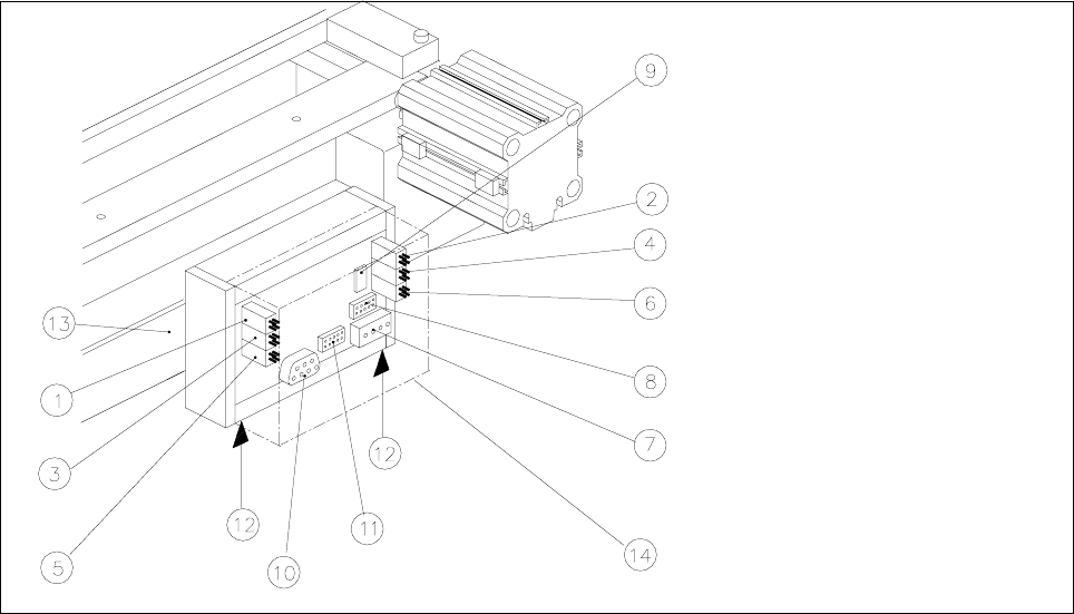
14.1.11 Exchanging the Control Unit
Fig. 14.1.9 Exchanging the Control Unit (Controller Board Assembly), Allocation of the Plug-and-Socket Connections
Key:
1) Drive of solenoid valve for cylinder 2 (left) 2) Drive of solenoid valve for cylinder 1 (right)
3) to the proximity switch on cylinder 2, FRONT 4) to the proximity switch on cylinder 1, FRONT
5) to the proximity switch on cylinder 2, BACK 6) to the proximity switch on cylinder 1, BACK
7) Cutter power supply 8) Drive of cutter
9) Service plug (only for Siemens service engineers) 10) CAN bus (only busy on HS-50 machines)
11) Coding plug (only busy on HS-50 machines 12) Spring-mounted elements to disconnect the
control box
13) Support bar 14) Cover
The cutter remains installed in the machine.
● Move the appropriate changeover table out of the machine or (in case of F4/F5) dismantle the component
table next to the WPC where applicable and remove the component table.
Service Manual SIPLACE 80S-20/F4/F5 14 Pneumatic Cutter
Edition 04/98 14.1 Pneumatic Cutter and Empty-Tape Duct
14 - 18
● Remove the cover from the controller board (see Fig. 14.1.9 -> 14).
● Disconnect all plug-and-socket connections of the controller board (see Fig. 14.1.9).
● Disconnect the control unit (box) off from the support bar by pushing both of the spring-mounted elements
away from the bar (see Fig. 14.1.9 -> 12).
● Install the new control unit (item no.: see Section 14.1.2) correctly rotated and positioned on the bar and
engage the unit.
● Restore all plug-and-socket connections in the correct allocation.
● Place the
FRYHU
back on the controller board.
● Make certain that the plug-and-socket connections are not subjected to tensile stress (see Fig. 14.1.10
-> 8).
● Perform the “Final Steps” (see Section 14.1.17).
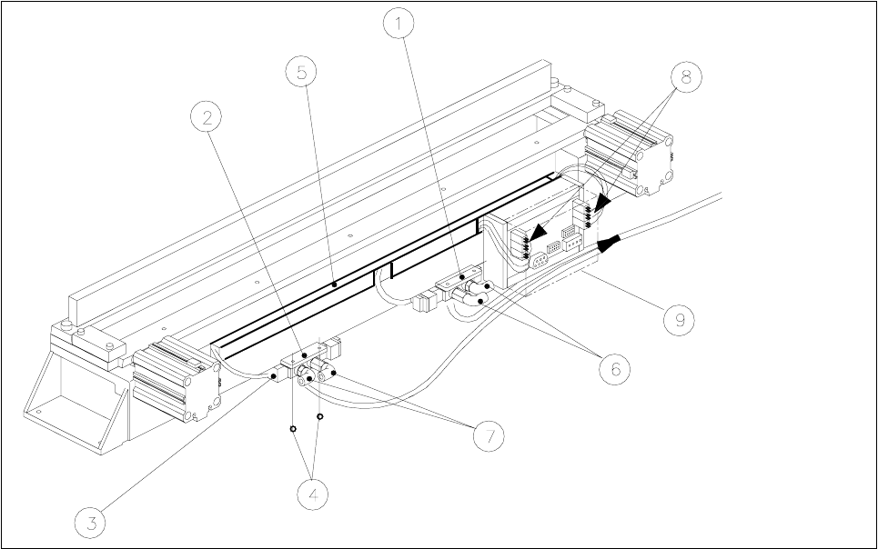
14.1.12 Exchanging the Solenoid Valve on Left or Right (and/or Cable)
Fig. 14.1.10 Exchanging the Solenoid Valve
Key:
1) Solenoid valve for cyinder 1, 2) Solenoid valve for cylinder 2,
incl. mounting plate incl. mounting plate
3) Plug-and-socket connection 4) Fastening for solenoid valve: 2 socket hex bolts each, M3 x 6
5) Cable pit cover 6) Compressed air hose for cylinder 1
7) Compressed air hose for cylinder 2 8) Cable/plug-and-socket connections: strain relief device
9) Cover