80S-20贴片机.pdf - 第477页
14 Pneumatic Cutter Service Manual SIPLACE 80S- 20/F4/F5 14.1 Pneumatic Cutter and Empty-Tape Duct Edition 04/98 14 - 19 The cutter UHPDLQVLQVWDO OHG in the ma chine . ● Move the ap propri ate changeov er table out of …
Service Manual SIPLACE 80S-20/F4/F5 14 Pneumatic Cutter
Edition 04/98 14.1 Pneumatic Cutter and Empty-Tape Duct
14 - 18
● Remove the cover from the controller board (see Fig. 14.1.9 -> 14).
● Disconnect all plug-and-socket connections of the controller board (see Fig. 14.1.9).
● Disconnect the control unit (box) off from the support bar by pushing both of the spring-mounted elements
away from the bar (see Fig. 14.1.9 -> 12).
● Install the new control unit (item no.: see Section 14.1.2) correctly rotated and positioned on the bar and
engage the unit.
● Restore all plug-and-socket connections in the correct allocation.
● Place the
FRYHU
back on the controller board.
● Make certain that the plug-and-socket connections are not subjected to tensile stress (see Fig. 14.1.10
-> 8).
● Perform the “Final Steps” (see Section 14.1.17).
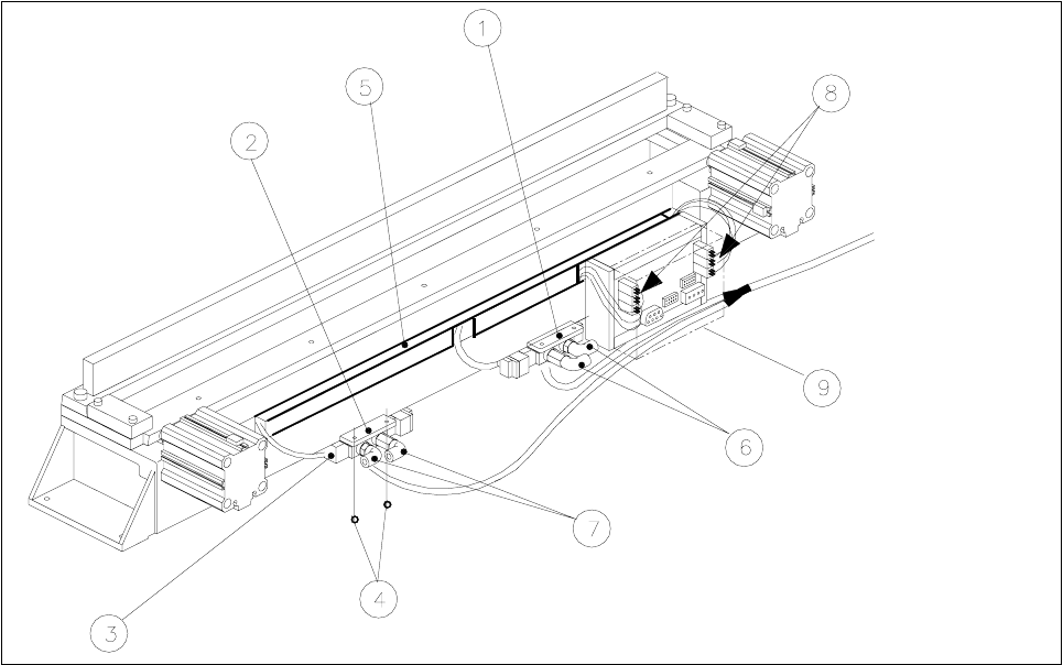
14.1.12 Exchanging the Solenoid Valve on Left or Right (and/or Cable)
Fig. 14.1.10 Exchanging the Solenoid Valve
Key:
1) Solenoid valve for cyinder 1, 2) Solenoid valve for cylinder 2,
incl. mounting plate incl. mounting plate
3) Plug-and-socket connection 4) Fastening for solenoid valve: 2 socket hex bolts each, M3 x 6
5) Cable pit cover 6) Compressed air hose for cylinder 1
7) Compressed air hose for cylinder 2 8) Cable/plug-and-socket connections: strain relief device
9) Cover
14 Pneumatic Cutter Service Manual SIPLACE 80S-20/F4/F5
14.1 Pneumatic Cutter and Empty-Tape Duct Edition 04/98
14 - 19
The cutter
UHPDLQVLQVWDOOHG
in the machine.
● Move the appropriate changeover table out of the machine or (in case of F4/F5) dismantle the component
table next to the WPC and remove the component table.
● ,IWKHFDEOHRIWKHVROHQRLGYDOYHLVIDXOW\
● Remove the cover from the control board (see Fig. 14.1.9 -> 14).
● Unplug the plug-and-socket connection of the faulty solenoid valve on the controller board (see Fig.
14.1.9).
● Remove the cover from the cable pit (see Fig. 14.1.9).
● Take out the cable and lay new the cable from the tape cutter to the valve (item no.: see Section
14.1.2).
● Make the
SOXJDQGVRFNHWFRQQHFWLRQ
on the board (see Fig. 14.1.9) and on the solenoid valve..
● Place the
FRYHU
back on the controller board.
● Install the cable pit cover and make certain there is no
WHQVLOHVWUHVV
on the plug-and-socket connec-
tions (see Fig. 14.1.10 -> 8).
● ,IWKHVROHQRLGYDOYHLVIDXOW\
● Undo the 2 compressed air connections on the solenoid valve.
● Undo the bolts fastening the solenoid valve (2 M3 bolts: see Fig. 14.1.10 -> 4) and remove the sole-
noid valve.
● Mount the new solenoid valve (item no.: see Section 14.1.2) in the correct position, as shown in Fig.
14.1.10.
-> The cable must feature a
WHQVLOHVWUHVVUHOLHIGHYLFH
(see Fig. 14.1.10 -> 8).
● Mount the short-stroke cylinder
FRPSUHVVHGDLUFRQQHFWLRQV
to the solenoid valve with the
FRUUHFW
DOORFDWLRQ
(see Fig. 14.1.7 -> 8).
● Perform the “Final Steps” (see Section 14.1.17).
14.1.13 Exchanging the Inductive Proximity Switch
The cutter remains installed in the machine.
● Move the appropriate changeover table out of the machine or (in case of F4/F5) dismantle the component
table next to the WPC and remove the component table.
● Remove the cover from the control board (see Fig. 14.1.9 -> 14).
● Disengage the plug-and-socket connection of the faulty proximity switch on the controller board (allocation:
see Fig. 14.1.9) and remove the cover from the cable pit (see Fig. 14.1.10 -> 5).
● Undo the bolt fastening the proximity switch on the short-stroke switch (1 bolt: see Fig. 14.1.7 -> 4 or 5)
and remove the proximity switch including the cable.
● Install the new proximity switch (item no.: see Section 14.1.2), ay the cable and restore the SOXJDQG
VRNNHWFRQQHFWLRQ
-> 0DNHFHUWDLQ there is QR WHQVLOHVWUHVVon the plug-and-socket connections (see Fig. 14.1.10 -> 8).
● Place the FRYHU back on the controller board.

Service Manual SIPLACE 80S-20/F4/F5 14 Pneumatic Cutter
Edition 04/98 14.1 Pneumatic Cutter and Empty-Tape Duct
14 - 20
● Install the cover of the cable pit and
PDNHFHUWDLQ
that the plug-and-socket connections are not subject to
WHQVLOHVWUHVV
(see Fig. 14.1.9 -> 8).
DANGER O O O
6
trictly adhere to the instructions in the DANGER text in Section 14.1.1.
Greater risk of accident exists with the SITEST program, particularly from the cutter.
● Load the SITEST program, actuate the individual cutting strokes and adjust the position of the new proxim-
ity switch in the process:
-> Adjustment of end positions: 1-2 mm before reaching the end position the LED on the proximity
switch must light up.
● If there is a deviation, move the proximity appropriately and screw it in the position determined.
● Perform the appropriate “Final Steps” (see Section 14.1.17).
14.1.14 Exchanging the Empty-Tape Duct
The empty-tape duct has to be exchanged if damaged (e.g., dented in) because the component table was
moved into the machine improperly.
● Move the appropriate changeover table out of the machine or (in case of F4/F5) dismantle the component
table next to the WPC if necessary and remove the component table.
● Undo the bolts fastening the empty-tape duct (see Fig. 14.1.1 -> 8, 9) and lift the empty-tape duct out of
the machine.
● Place the new empty-tape duct (item no.: see Section 14.1.2) on the 2 pins and check the height vis-a-vis
the cutter:
-> The lower edge of the empty-tape duct must be as close as possible to the movable blade on its entire
length:
-> The maximum permissible distance is 0.5 mm.
● If there is an deviation, lift the empty-tape duct out again and insert the appropriate spacer discs (item
no.: see Section 14.1.2) under the 2 pins (see Fig. 14.1.1 -> 10).
● Tighten the bolts holding the empty-tape duct (2 bolts).
● Perform the appropriate “Final Steps” (see Section 14.1.17).