80S-20贴片机.pdf - 第72页
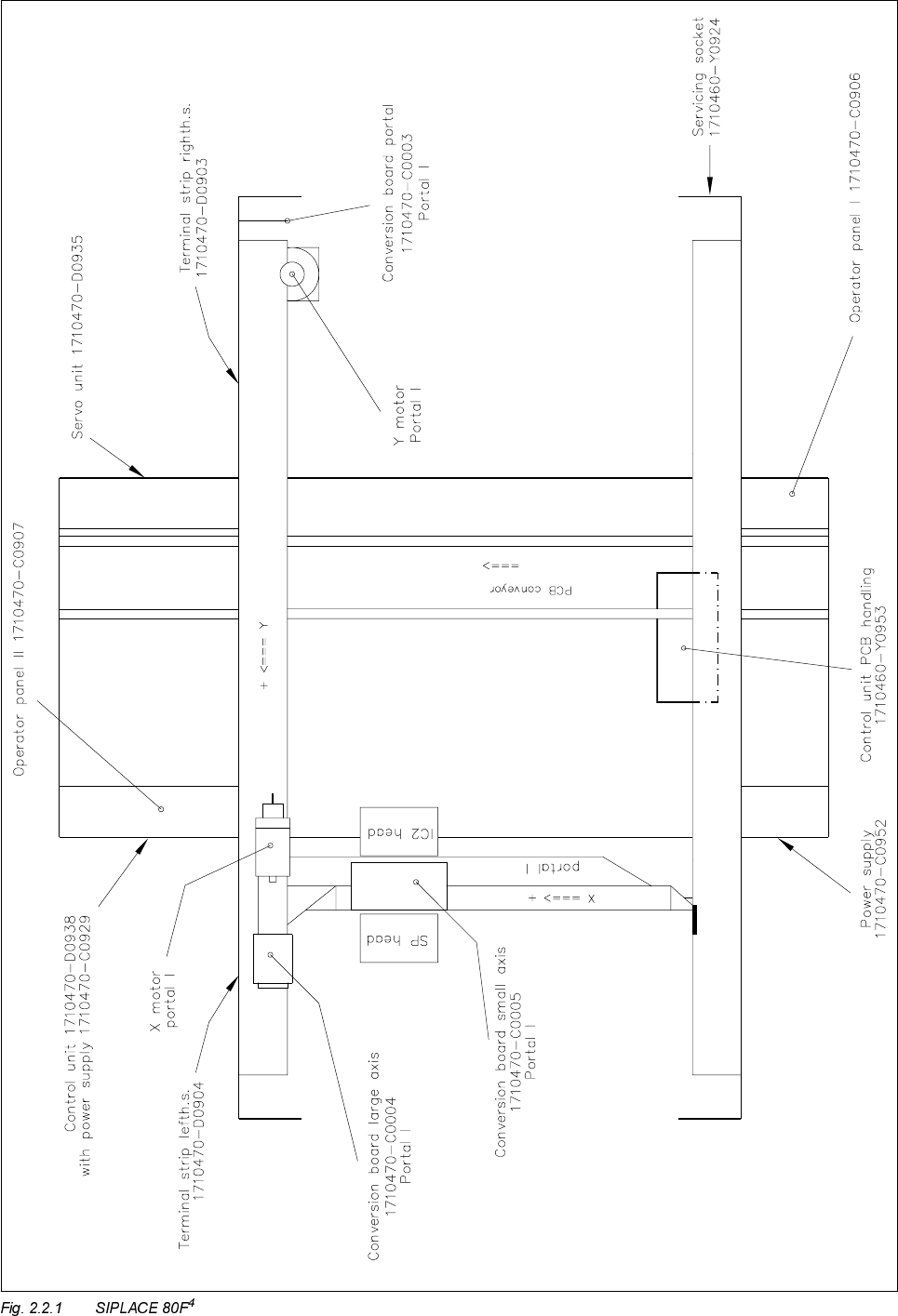
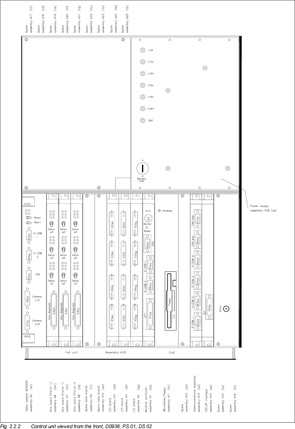
2 Overview Diagrams S IPLACE 80S-20/F4 Service Manual 2.2 Electrical System SIPLACE 80F4 E dition 03/97 2 - 30 Machine overview

SIPLACE 80S-20/F4 Service Manual 2 Overview Diagrams
Edition 03/97 2.2 Electrical System SIPLACE 80F4
2 - 29
(OHFWULFDO6\VWHP6,3/$&()
6,3/$&(6GLDJUDPVZKLFKDOVRDSSO\WR6,3/$&()
1 Control unit base viewed from the front see Fig. 2.1.3, Page 6
2 Control unit base viewed from the back see Fig. 2.1.4, Page 7
3 Control unit base axis rear panel see Fig. 2.1.5, Page 8
4 Power supply control unit see Fig. 2.1.6, Page 9
5 Cable harness set control unit see Fig. 2.1.7, Page 10
6 Power supply see Fig. 2.1.13, Page 16
7 Power supply see Fig. 2.1.14, Page 17
8 Power supply see Fig. 2.1.15, Page 18
9 Control unit PCB handling see Fig. 2.1.18, Page 21
10 Control unit PCB handling see Fig. 2.1.19, Page 22
11 Control unit PCB handling see Fig. 2.1.20, Page 23
12 Conversion board portal see Fig. 2.1.21, Page 24
13 Conversion board large axis see Fig. 2.1.22, Page 25
14 Conversion board small axis see Fig. 2.1.23, Page 26
2 Overview Diagrams SIPLACE 80S-20/F4 Service Manual
2.2 Electrical System SIPLACE 80F4 Edition 03/97
2 - 30
Machine overview
SIPLACE 80S-20/F4 Service Manual 2 Overview Diagrams
Edition 03/97 2.2 Electrical System SIPLACE 80F4
2 - 31