N7205A119B04(1)DX Wiring Diagram.pdf - 第62页
1aF101 FK5.5-5 JST 3aF101 5aF101 -F101 BW50RAGU-3P030 1 2 3 4 5 6 Fuji Electric FA Components & Systems UaT001 AI6-12YE PHOENIX CONTACT VaT001 AI6-12YE PHOENIX CONTACT CPTUT001 AI6-12YE PHOENIX CONTACT CPTVT001 CPTWT…
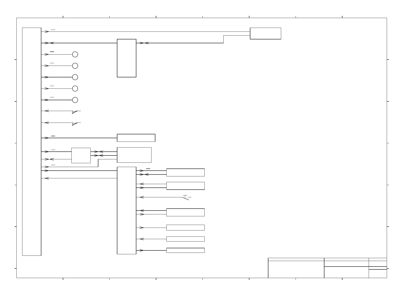
M
Vacuum Pump (Bst)
-G211B
Head
-S0730,-S0537
Power
Unit #2
+A11B
CPU
Box
+A01
3~ 200 V
M
Bottom Cooling Fan 1 (Bst)
-G112
Cart Unit
(BF,BR)
48 V
Valve (Bst)
-R4*
Sensor (Bst)
-B1*
24 V
Safety Cover SW (Bst)
-S311B~-S312B
Out of Work Light (BF,BR)
-B211B,-B212B
+A41B,+A42B
+A21B,+A22B
Dust Box (BF,BR)
-B1410,-B1510
Conveyor
Unit (Bst)
+A31B
24 V
-B1446,-B1447
Transportation Opening
Sensor
24 V
-K321B,-K322B
M
Roof Cooling Fan 1 (Bst)
-G104
(BF,BR)
-S315B~-S316B
Feeder Safety Cover SW (Bst)
Nozzle Changer (BF,BR)
-B0*B,-B1*B
-K323B,-K324B
24 V
(Bst)
CN Board
: Transfer
#3,#4
CN Board
: IO #3,#4
1~ 200 V
24 V
3~ 200 V
24 V
1
-G1434
-G1435
1
1
1
1
-B10B*,-B10A*
-S0736,-S1537
Operation Switch
2
2
M
Roof Cooling Fan 2 (Bst)
-G106
24 V
3
M
Bottom Cooling Fan 2 (Bst)
-G113
3
24 V
Panasonic Factory Solutions Co.,Ltd. パナソニック ファクトリーソリューションズ株式会社
Name
Drawing No.
Loc. No.
F4K1020-05A
1
2 3 4 5 6 7 8
A
B
C
D
E
F
1 2 3 4 5 6 7 8
A
B
C
D
E
F
Page. No.
Main Body Wiring (NPM-DX)
(Block Diagram 3)
MTKA001071+004AD
P004
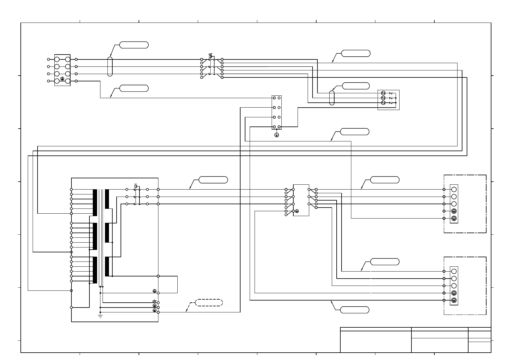
1aF101
FK5.5-5
JST
3aF101
5aF101
-F101
BW50RAGU-3P030
1
2
3
4
5
6
Fuji Electric FA Components & Systems
UaT001
AI6-12YE
PHOENIX CONTACT
VaT001
AI6-12YE
PHOENIX CONTACT
CPTUT001
AI6-12YE
PHOENIX CONTACT
CPTVT001
CPTWT001
+A11A
Power Unit #1(Ast)
L11d2X1A
AI6-12YE
PHOENIX CONTACT
L21d1X1A
L31d1X1A
L1
L2
L3
PE
L1
L2
L3
-X101
TB-X115(Y002761)
1 1
2 2
3 3
4 4
PHOENIX CONTACT
L1bX101
AI6-12YE
PHOENIX CONTACT
L2bX101
L3bX101
EX101
ET001
AI6-12YE
PHOENIX CONTACT
EV001
5.5-S4
5aV001 2aV001
1aV001
FK5.5-5
JST
4aV001
FK5.5-5
JST
6aV001 3aV001
-V001
FTA-40-335-U
4
5
6
1
2
3
COSEL
-F201
LV550DI-U4(250)
BK
BK
BK
GN/YE
Okaya Electric Industries
AWG8/16 600V VW-1(BK)
Ed4X1B
Ed4X1A
2aF101
FK5.5-5
JST
2bF101
4bF101
6bF101
4aF101
6aF101
-X111A
L11
L21
L31
L11d2X1B
AI6-12YE
PHOENIX CONTACT
L21d1X1B
L31d1X1B
Ec4X1B
-X111B
L11
L21
L31
1bV001
2bV001
3bV001
-X001
N510013514AA
Asada Metal Industry
GN/YE
BK
BK
BK
GN/YE
BK
BK
BK
WaT001
AI6-12YE
PHOENIX CONTACT
UL1015 10AWG
UL1015 10AWG
UL1015 10AWG
UL1015 10AWG
UL1015 10AWG
UL1015 10AWG
UL1015 10AWG
UL1015 10AWG
BK
BK
BK
UL1015 10AWG
UL1015 10AWG
UL1015 10AWG
AH-6 ORANGE AWG7/16in
MTKC002423AC
MTKC002424AB
MTKC002425AC
N610161405AB
MTKC002427AD
MTKC002428AD
MTKC002429AC
MTKC002425**
BZ6N10D
CPT
CP1(30A)
TB-A
TB-A
TB-A
PRI
SEC
CPT
TB-A
TB-A
TB-A
-T001
TE3N-8K-GR/TD-19864
U1 480V
U2 420V
U3 400V
U4 380V
U5 220V
U6 200V
V1 480V
V2 420V
V3 400V
V4 380V
V5 220V
V6 200V
W1 480V
W2 420V
W3 400V
W4 380V
W5 220V
W6 200V
N1
CPTU
CPTV
CPTW
N1
TAISEI DENKI
+A11B
Power Unit #2(Bst)
MTKC002430AD
MTKC002431AD
UL1015 12AWG
UL1015 10AWG BK BK
UL1015 10AWG BK BK
UL1015 10AWG BK BK
UL1015 10AWG GN/YE GN/YE
UL1015 10AWG GN/YE GN/YE
UL1015 12AWG
UL1015 12AWG
UL1015 12AWG
UL1015 12AWG
UL1015 12AWG 2
UL1015 12AWG
2
UL1015 12AWG
2
UL1015 12AWG
2
UL1015 10AWG BK BK
UL1015 10AWG BK BK
UL1015 10AWG BK BK
UL1015 10AWG GN/YE GN/YE
AI4-10GY
2
AI4-10GY
2
NF3030C-SVB
2
SOUSHIN ELECTRIC
2
3
1
5
6
4
FK5.5-S4
2
FK5.5-S4
2
3
3
2
2 1
2
1
3
5
6
2
7
8 4
E4X001
5.5-S4
JST
E5X001
5.5-S4
JST
E6X001
5.5-S4
E7X001
5.5-S4
E8X001
5.5-S4
L11c1X1A
L21c1X1A
L31c1X1A
Ed1X1A
2
2
2
2
L11c1X1B
L21c1X1B
L31c1X1B
Ed4X1B
2
2
2
2
2
2
2
2
2
Ec1X1B
2
2
1
2
3
2 1 3
2
2 1 3
2 1 3
AH-6 BLACK AWG5/16in
4
Panasonic Factory Solutions Co.,Ltd. パナソニック ファクトリーソリューションズ株式会社
Name
Drawing No.
Loc. No.
F4K1020-05A
1
2 3 4 5 6 7 8
A
B
C
D
E
F
1 2 3 4 5 6 7 8
A
B
C
D
E
F
Page. No.
Main Body Wiring (NPM-DX)
(AC200V Input)
MTKA001071+005AE
P005
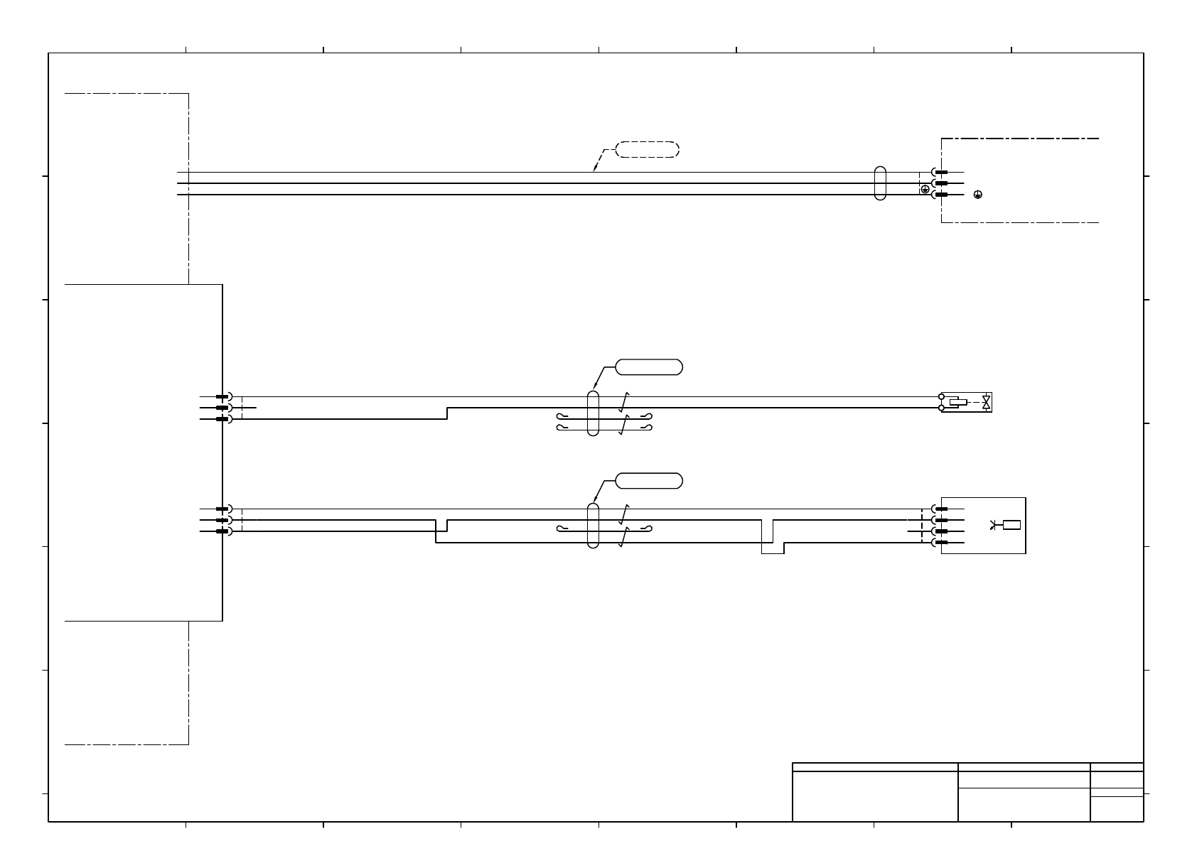
+A01
CPU Box
-R301
AC30X-03-X2857
SMC
Main Air Valve
+
AI0.5-6WH
PHOENIX CONTACT
-
(1.0mm2-3C)
1
W
CPUAC
S8G0307
BU
BN
GN/YE
Kawasaki Electric Wire
L11
L21
L11c2X1
L21c1X1
1
W
Ec4X1
CNAIR
24VOUT
IN116
24GND
JST
AIR_K311A
PAP-03V-S
3
2
1
Main Air Pressure
p
24V
OUT1
N.C.
GND
p
1
2
3
4
BK/WH
BK
RD/WH
RD
2464C(BPF)VVP AWG#24×2P-B
Note1) Connector Pin arrangement is not sequential.
MTKC000686**
CNVL
24VOUT
N.C.
24GND
JST
VL_K311A
PAP-03V-S
3
2
1
BK/WH
BK
MTKC002432AE
MTKC000684AE
-K311A
PNF0C2
+A11A
Power Unit #1(Ast)
SIO Board #1
1
2
3
1
2
3
2
RD/WH
RD
2464C(BPF)VVP AWG#24×2P-B
2464-1061/ⅡA(PF)LF 1P×20AWG
2
2464-1061/ⅡA(PF)LF 2P×24AWG
2
1R
2R
2
L21
L31
2
L21c5X1 2
Ed3X1
2
BN
BU
3
3
2 3
JST
B0116R
PAP-04V-S
4
3
2
1
Note1)
ISE30A-C4H-N-MB
SMC
PAP-05V-S
3
3
DP-002Z-J-H2
Panasonic
-B0116
3
3
Panasonic Factory Solutions Co.,Ltd. パナソニック ファクトリーソリューションズ株式会社
Name
Drawing No.
Loc. No.
F4K1020-05A
1
2 3 4 5 6 7 8
A
B
C
D
E
F
1 2 3 4 5 6 7 8
A
B
C
D
E
F
Page. No.
Main Body Wiring (NPM-DX)
(Cpu Box, Main Air Valve, Pressure Sensor)
MTKA001071+006AE
P006
4
4