00192267-02 - 第40页
HS-50 Changeover Instructions Cont rol PCB Convey or 2.6 Options v acuum tooling and ceram ic substrate centering 04/2002 Issue 40 2SWLRQVYDF XXPWRROLQJ DQGFHUDPLFVXEVWUDWH FHQWHULQJ 3ULRU+6 PDFKLQH…
Changeover Instructions Control PCB Conveyor HS-50
04/2002 Issue 2.5 Schematics and Settings
39
/RDGLQJ)LUPZDUH&RQYH\RU
The conveyor control is not supplied with firmware. Correspondingly the firmware must be in-
stalled on it.
The firmware conveyor is on the supplied disk 00356219-01 for the software version 501.xx.
From the software version 502 please create an installation disk with the aid of the supplied instal-
lation CD (see installation instructions in the software version description).
How to install the firmware conveyor:
➠ insert installation disk with firmware conveyor in disk drive machine controller (M54).
➠ turn on machine.
To display, change to the view on the monitor.
MS-DOS is started on the machine controller. Finally the firmware is automatically transmitted
via CAN-Bus to the conveyor control. With double conveyor both conveyor controls are auto-
matically reinstalled.
➠ Following successful download, the version and the date of creation of the installed software
are displayed.
Importance of the LEDs on the conveyor control:
– red LED "Fail" - this LED
* lights up continously the module is defect
* is continuously lit up for approx. 10 seconds when turning on
* flashes - conveyor control is in reinstall mode (or is waiting for the reloading of the firmware)
– green LED "RUN", this LED
* flashes - firmware conveyor control is running
– yellow LED "CAN", this LED
* lights up briefly if a CAN telegram has been received
* lights up continously during reinstallation of the firmware.
HS-50 Changeover Instructions Control PCB Conveyor
2.6 Options vacuum tooling and ceramic substrate centering 04/2002 Issue
40
2SWLRQVYDFXXPWRROLQJDQGFHUDPLFVXEVWUDWH
FHQWHULQJ
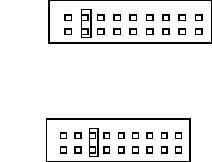
3ULRU+6PDFKLQHVXSWRDSSUR[DSULO5HSODFLQJD763
The jumper on the option plug X34 resp. X35 on the transport conversion board has to be set as
follows.
&HUDPLFVXEVWUDWHFHQWHULQJ
X34 Pin 3-4 / X35 Pin 3-4
9DFXXPWRROLQJ X34 Pin 5-6 / X35 Pin 5-6
➠ The coder plugs X22/X23 ao / ap with the options are no longer required after plugging the
jumpers!
2
1
2
1
Changeover Instructions Control PCB Conveyor HS-50
04/2002 Issue 2.6 Options vacuum tooling and ceramic substrate centering
41
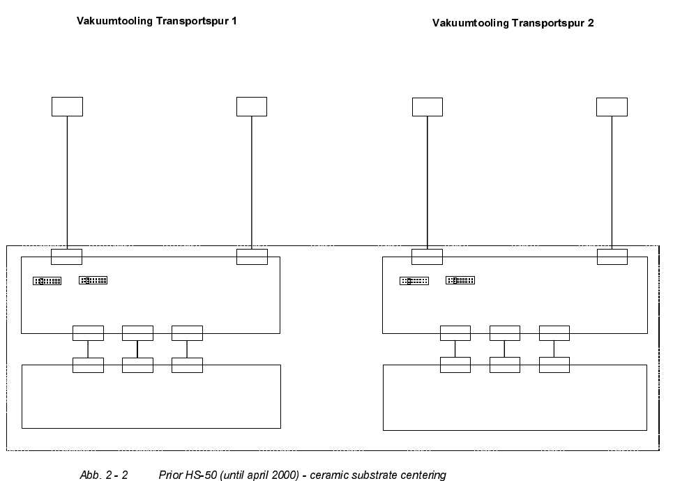
&HUDPLF6XEVWUDWH&HQWHULQJ
The following diagram shows the wiring of the option FHUDPLFVXEVWUDWHFHQWHULQJ
8PVHW]SODWLQH7UDQVSRUW
X24ao
X24ao
X25ao
X25ao
Z 1 Z 2
Ventil
Vakuum-
tooling 1
(Transport 1)
00 357 282
Ventil
Vakuum-
tooling 2
(Transport 1)
00 358 283
Umsetzplatine Transport 2 (an/ap)
00 348 267
Umrüstsatz Steuerung komplett HS50 Einfachtransport (Doppeltransport) / Mat.-Nr.: 00 349 885 (00 349 886)
Umsetzplatine Transport 1 (am/ao)
00 348 267
X13
X13
X12
X12
X11
X11
X33
X33
X32
X32
X31
X31
Transportsteuerung Transport 1 (ao)
00 349 302 (00 353 442)
X34* X35*
2
1
2
1
* Jumper auf X34/X35 Pin 5-6 müssen gesteckt sein;
Codierung für Vakuumtooling
X13
X13
X12
X12
X11
X11
X33
X33
X32
X32
X31
X31
Transportsteuerung Transport 2 (ap)
00 349 302 (00 353 442)
X34* X35*
2
1
2
1
* Jumper auf X34/X35 Pin 5-6 müssen gesteckt sein;
Codierung für Vakuumtooling
0
0
3
5
7
2
8
2
0
0
3
5
7
2
8
3
X24ap
X24ap
X25ap
X25ap
Z 4 Z 3
Ventil
Vakuum-
tooling 4
(Transport 2)
00 357 282
Ventil
Vakuum-
tooling 3
(Transport 2)
00 358 283
0
0
3
5
7
2
8
2
0
0
3
5
7
2
8
3