HS50_advance_level 1_20200522_221201 (1).pdf - 第107页
Studen t Guide HS-50 A dvanced I 06/200 2 Edition 5 DLM1 C&P Head 15 5.1 .5.4 Status 7 S egm ent d ispl ay co mpared to the L ED Dis play The status of the PRO CESSO R BOARD 80C51 5C FW is indicat ed on t he 7-segmen…
06/2002 Edition Student Guide HS-50 Advanced I
5 DLM1 C&P Head
14
5.1.5.3 New Jumper Setting on the modular head board
Set the DIP switch on the processor board on the basis of the following data.
You will see the position of the switch in Fig. 5.1 - 11 , below.
5
Fig. 5.1.10 Table: DIP Switch
The wiring of the switch depends on the placement machine involved: 5
Jumper 1: ON -> CAN matching resistor on the placement head is set
(S-20, F4, F5), S-23, S-25 HM, F5 HM.
OFF ->CAN_matching resistor is not wired on the head (HS-50 default)
Jumper 2: ON -> Setting during the download
OFF -> Default status
Jumper 3: ON -> Test mode
OFF -> Default status
Jumper 4: ON -> Test mode (setting of CAN ID)
OFF -> Default status
Jumper 5: ON -> Default status
Jumper 6: ON -> Default status
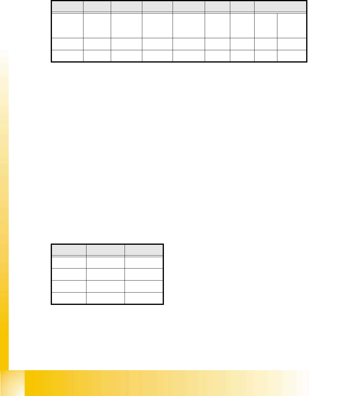
Jumper 7, 8: CAN_ID:
Fig. 5.1 - 11 Table: Gantries CAN_Adress
Standard OFF OFF OFF OFF ON ON CAN_Adress
Position
of switch
1
CAN_R120
2
EPROM_WE
3
Te s t_M o de
4
CAN_ERR_
SWITCH
5
Jumper 5
6
Jumper 6
7
CAN_ID1
8
CAN_ID0
ON X X
OFF X X X X
Gantries Jumper 7 Jumper 8
Gantry 1 ON ON
Gantry 2 ON OFF
Gantry 3 OFF ON
Gantry 4 OFF OFF
Student Guide HS-50 Advanced I 06/2002 Edition
5 DLM1 C&P Head
15
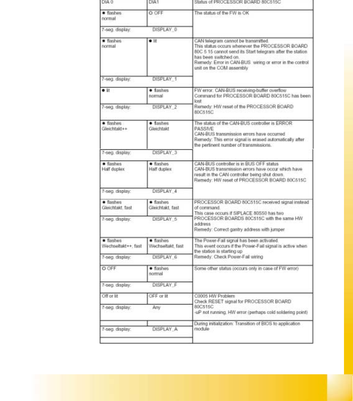
5.1.5.4 Status 7 Segment display compared to the LED Display
The status of the PROCESSOR BOARD 80C515C FW is indicated on the 7-segment display
(see Fig. 5.1 - 9). To enable you to compared the displays with old heads, the LED displays
(seeFig. 5.1 - 8) have also been listed in the table.
Fig. 5.1 - 12 Status 7segment display and LED display

06/2002 Edition Student Guide HS-50 Advanced I
5 DLM1 C&P Head
16
5.2 Pick up Cycle of the C&P-Head
5.2.1 Steps when picking up and placing components
– A PCB moves into the placement area of the PCB conveyor.
– The right-hand revolver head picks up components from the feeder modules.
– The left-hand revolver head waits for the fiducial measurement.
– Once the fiducial measurement is complete, the right-hand revolver head places components
while the left-hand revolver head picks up further components.
– The right-hand revolver head picks up components, and so on.
5.2.1.1 Position and function of the individual star stations (see Fig. 5.1 - 5)
Star station 1 5
Pick-up cycle 5
The nozzle is lowered onto the component. Once the valve positioning unit has opened the vac-
uum circuit to the nozzle, the nozzle draws up the component and removes it from the feeder mod-
ule. 5
Star station 3 5
The valve positioning unit closes the vacuum channel to the nozzle. Defective components are
detached from the nozzle with a short burst of compressed air and are discarded. 5
Star station 7 5
The component is optically centered. 5
Star station 9 5
Pick-up cycle 5
The nozzle is rotated to the pick-up position. 5
5
5
5