HS50_advance_level 1_20200522_221201 (1).pdf - 第115页
Studen t Guide HS-50 A dvanced I 06/200 2 Edition 5 DLM1 C&P Head 23 5. 2.9 P CB pos ition re cog nit ion run t o t he P CB no min al p osi tio n – PCB pos it i on recognition with gantry 4(placement area 1) and gant…
06/2002 Edition Student Guide HS-50 Advanced I
5 DLM1 C&P Head
22
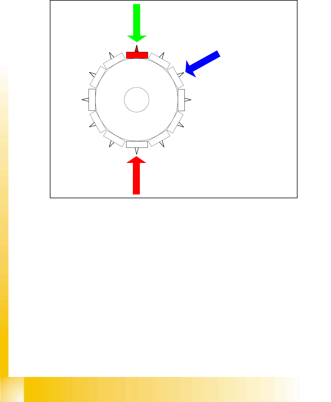
5.2.8 Pick up 7th component
Fig. 5.2 - 7 Pick up 7th component
– Vision system:
component on segment 1 of the gantry is centered
– Dp-station:
turn nozzle 11 to Pick up angle
– pick up / placement station:
pick up 7th component
Star position
Digit: 72.000
Angle: 180 °
1
2
1
1
10
9
8
7
6
5
1
2
3
4
Student Guide HS-50 Advanced I 06/2002 Edition
5 DLM1 C&P Head
23
5.2.9 PCB position recognition run to the PCB nominal position
– PCB position recognition with gantry 4(placement area 1) and gantry 2(placment area 2) is
done after the 7th component is picked up and nozzle 11 is turned to the pick up the angle.
– The gantry axes move the PCB camera to the theoretical fiducial position. The camera takes
the picture of the fiducial and the vision system calculates the center position.
The centered fiducial define now the actual position of the board.
– The camera takes the picture of the fiducial and the vision system calculates the center posi-
tion of this picture.
– The 2nd calculation is the deviation between nominal and calculated fiducial position.
– All board fiducials are optically centered with this procedure.
– This data is sent to the machine controller
– The correction values are calculated for the X, Y and the angular position of the PCB .
– Now the gantry axes move the placement head to the next pick up position
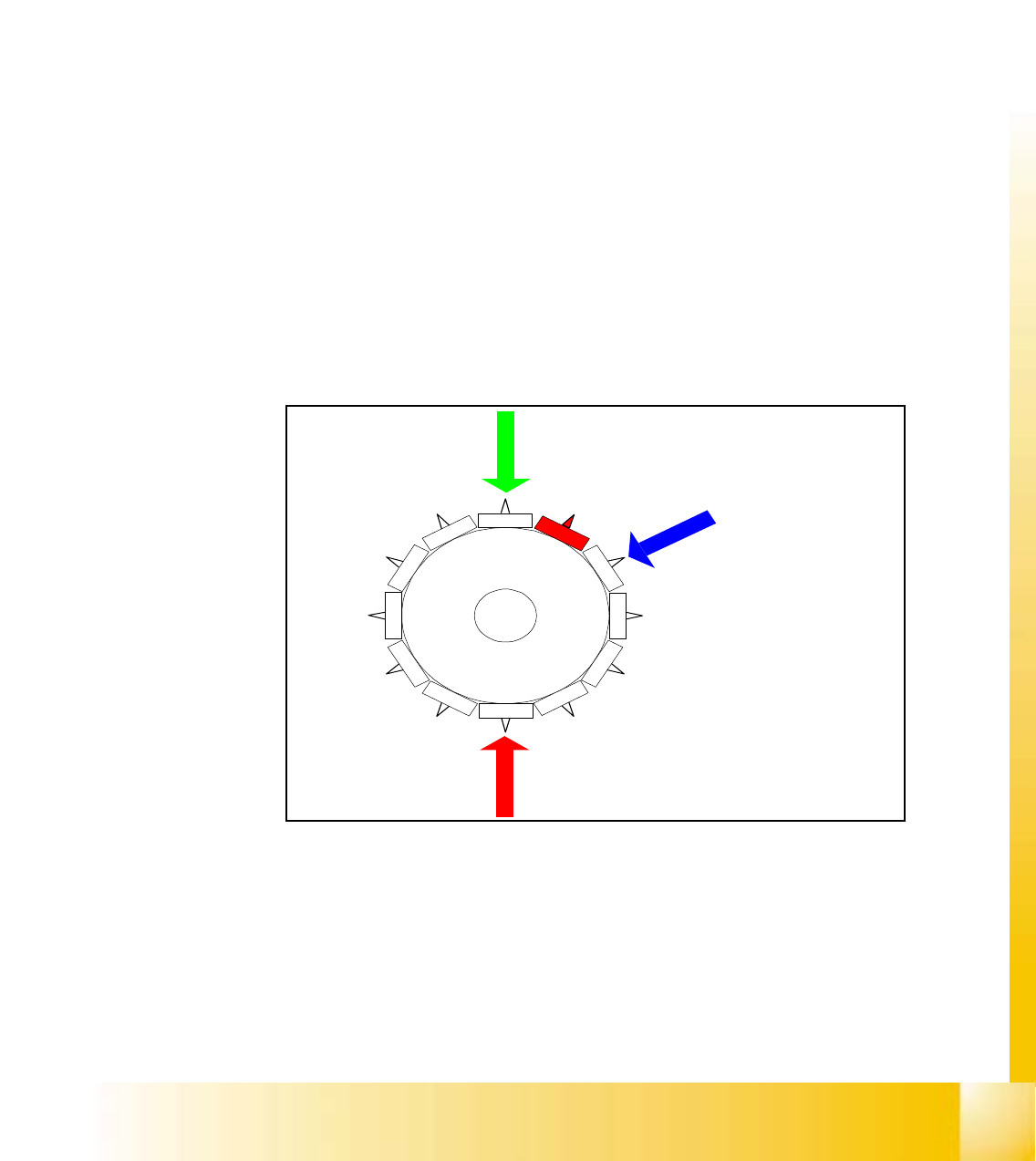
5.2.10 Pick up 8th component
Fig. 5.2 - 8 Pick up 8th component
– Vision system:
component on segment 2 of this gantry is centered
– Dp-station:
turn nozzle 12 to Pick up angle
– pick up / placement station:
pick up 8th component
Star position
Digit: 84.000
Angle: 210 °
1
2
11
1
0
9
8
7
6
5
1
2
3
4
06/2002 Edition Student Guide HS-50 Advanced I
5 DLM1 C&P Head
24
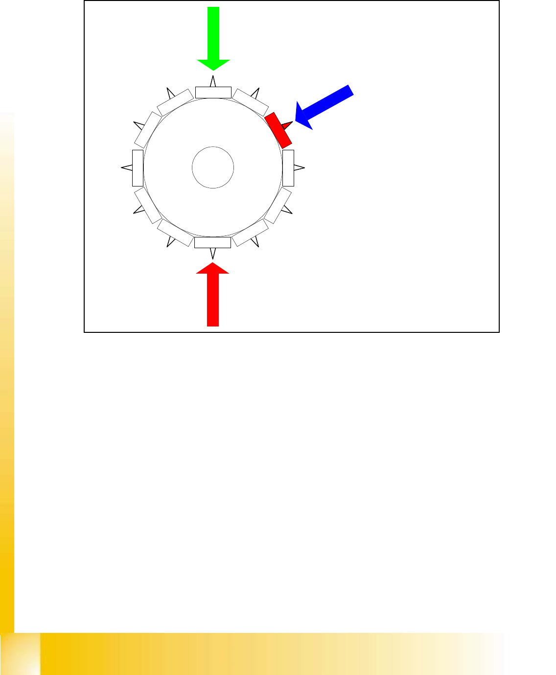
5.2.11 Pick up 9th Component
Fig. 5.2 - 9 Pick up 9th component
– Vision system:
optical centering of the 3rdcomponent
– Dp-station:
turn 1st component to the placement angle
– pick up / placement station:
pick up 9th component
The process continues with the remaining components being picked up, centred and turned to the
corrected placement angle
Star position
Digit: 96.000
Angle: 240 °
12
1
1
1
0
9
8
7
6
5
1
2
3
4