HS50_advance_level 1_20200522_221201 (1).pdf - 第117页
Studen t Guide HS-50 A dvanced I 06/200 2 Edition 5 DLM1 C&P Head 25 5.2. 12 Pick u p 12th c o mpo n en t Fig. 5.2 - 10 P i ck up 12 th co mpone nt – Vision system: optical centering of the 6th com ponent – D p- st a…
06/2002 Edition Student Guide HS-50 Advanced I
5 DLM1 C&P Head
24
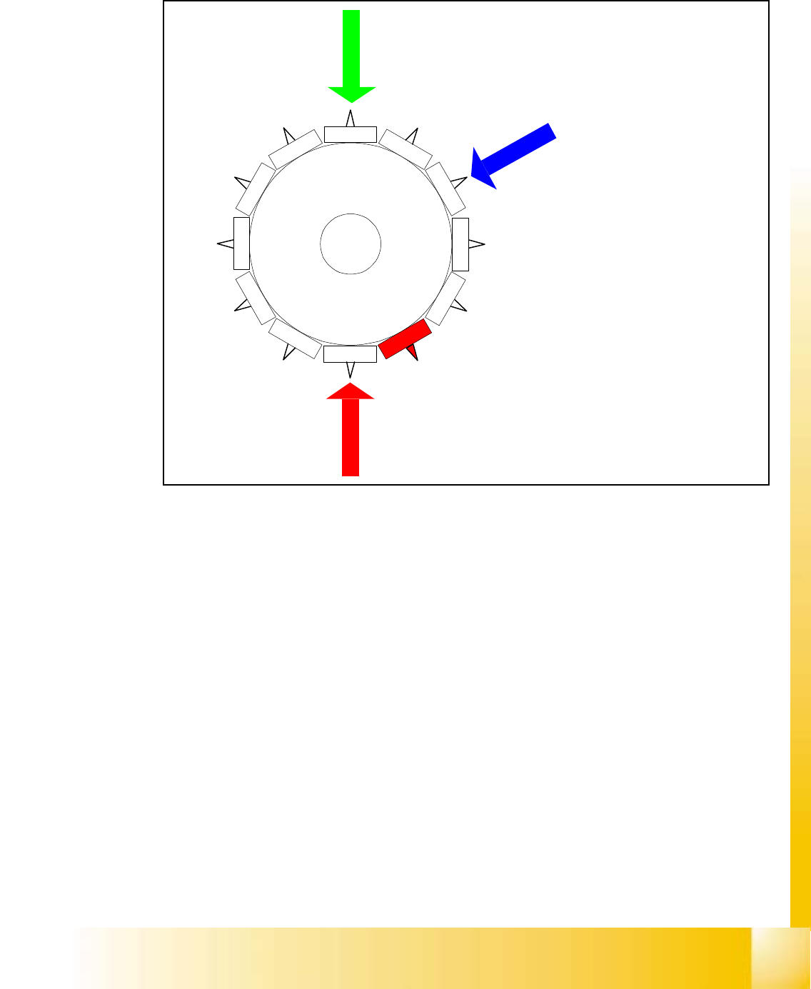
5.2.11 Pick up 9th Component
Fig. 5.2 - 9 Pick up 9th component
– Vision system:
optical centering of the 3rdcomponent
– Dp-station:
turn 1st component to the placement angle
– pick up / placement station:
pick up 9th component
The process continues with the remaining components being picked up, centred and turned to the
corrected placement angle
Star position
Digit: 96.000
Angle: 240 °
12
1
1
1
0
9
8
7
6
5
1
2
3
4
Student Guide HS-50 Advanced I 06/2002 Edition
5 DLM1 C&P Head
25
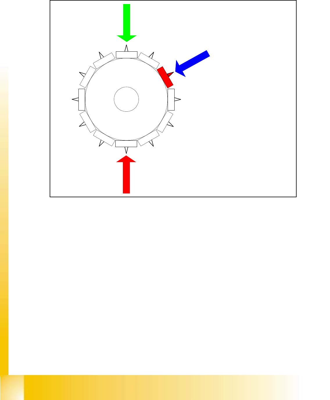
5.2.12 Pick up 12th component
Fig. 5.2 - 10 Pick up 12th component
– Vision system:
optical centering of the 6th component
– Dp-station:
turn 4th component to the placement angle
– pick up / placement station:
pick up 12th component
– communication with the component table:
activate tape cutter
– synchronization:
after picking the 12th component this gantry is waiting for placement enable signal from MC.
Star position
Digit: 132.000
Angle: 330 °
12
1
1
1
0
9
8
7
6
5
1
2
3
4

06/2002 Edition Student Guide HS-50 Advanced I
5 DLM1 C&P Head
26
5.3 Placement Cycle of the C&P-Head
5.3.1 Steps when placing components
– A PCB moves into the placement area of the PCB conveyor.
– The right-hand revolver head picks up components from the feeder modules.
– The left-hand revolver head waits for the fiducial measurement.
– Once the fiducial measurement is complete, the right-hand revolver head places components
while the left-hand revolver head picks up further components.
– The right-hand revolver head picks up components, and so on.
5.3.1.1 Position and function of the individual star stations (see Fig. 5.1 - 5)
Star station 1 5
Placement cycle 5
The valve positioning unit closes the vacuum channel to the nozzle. The nozzle, together with the
component, is lowered onto the PCB that has been moved into place. A short burst of compressed
air detaches the component from the nozzle and places it on the PCB. 5
Star station 3 5
The valve positioning unit closes the vacuum channel to the nozzle. Defective components are
detached from the nozzle with a short burst of compressed air and are discarded. 5
Star station 7 5
The component is optically centered. 5
Star station 9 5
Placement cycle 5
The placement angle of the component is corrected or the correct placement angle of the compo-
nent is set. 5