HS50_advance_level 1_20200522_221201 (1).pdf - 第121页
Studen t Guide HS-50 A dvanced I 06/200 2 Edition 5 DLM1 C&P Head 29 5.3. 4 Placin g 7th Co mponent Fig. 5.3 - 3 Plac ing 7t h c ompon ent – Vision system: optical c entering of the 1st component on the other gantry …
06/2002 Edition Student Guide HS-50 Advanced I
5 DLM1 C&P Head
28
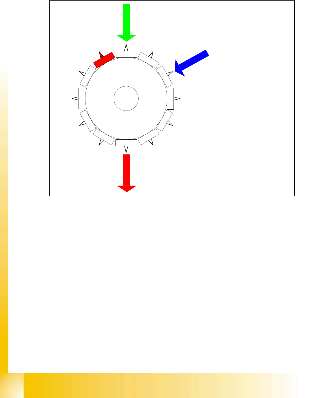
5.3.3 Placing 6th component
Fig. 5.3 - 2 Placing 6th component
– Vision system:
optical centering of the 12th component
– Dp-station:
turn 10th component to the placement angle
– pick up / placement station:
place 6th component
– synchronization:
communication with the MVS for the optical centering of component´s. Access to the MVS is
given to the „picking gantry“. IE the other gantry on an S machine now starts centering.
Star position
Digit: 60.000
Angle: 150 °
12
1
1
1
0
9
8
7
6
5
1
2
3
4

Student Guide HS-50 Advanced I 06/2002 Edition
5 DLM1 C&P Head
29
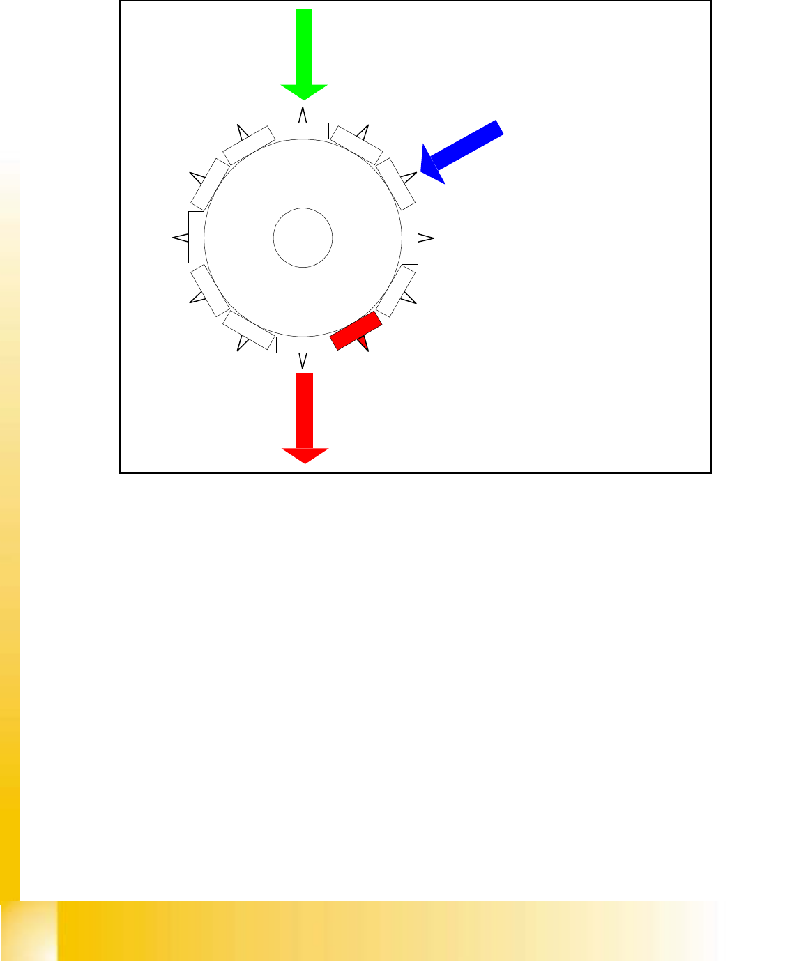
5.3.4 Placing 7th Component
Fig. 5.3 - 3 Placing 7th component
– Vision system:
optical centering of the 1st component on the other gantry
– Dp-station:
turn 11th component to the placement angle
– pick up / placement station:
place 7th component
Star position
Digit: 72.000
Angle: 180 °
1
2
1
1
10
9
8
7
6
5
1
2
3
4
06/2002 Edition Student Guide HS-50 Advanced I
5 DLM1 C&P Head
30
5.3.5 Placing 12th Component
Fig. 5.3 - 4 Placing 12th component
– Vision system:
optically centering of the 6th component on the other gantry
– Dp-station:
turn 4th component to the pick up angle
– pick up / placement station:
place 12th component
– synchronization:
after placing the 12th component of this gantry placement enable signal is returned to MC.
Star position
Digit: 132.000
Angle: 330 °
12
1
1
1
0
9
8
7
6
5
1
2
3
4