HS50_advance_level 1_20200522_221201 (1).pdf - 第124页
06/2002 E dition Studen t Guide H S-50 Advance d I 5 DLM1 C&P H ead 32 5. 4 C&P Head dis- and reass embly 5.4. 1 Points to note b efore start in g ser vicing wor k ... ➠ End all placemen t operations on the place…

Student Guide HS-50 Advanced I 06/2002 Edition
5 DLM1 C&P Head
31
5.3.6 Pick up and placement cycle for the next components...
– After all the components of the first head cycle are placed onto the board,the gantry axes move
the placement head to the pick up position of the next feeder.
– The next pick up cycle for components 7 to 12 is executed.
– And so on and so on.....
– If necessary the machine executes repair cycles.
5.3.7 Segment with a „defective component“
If the optical centering of a component fails (Ident.error) or the vacuum check before placement
fails (Vacuum error) the component is not placed and remain on the nozzle;
– the turning station turn now this nozzle to the pick up angle of the new component when this
segment is in turning position.
If this segment is in pick up position:
– the reject procedure is activated and
– the star-axis moves on for two segments
– X-/Y-axes move to their reject position
– the component is rejected by an air kiss
– the star-axis turns two segments back and
– the new component is picked
This rejected component is placed after all placement cycles by a „repair cycle“.
5.3.8 PCB placement finished
– All components are placed at the corrected placement positions at the programmed board po-
sitions.
– After placing the last component with the pickt & Place head the gantry axes move the place-
ment heads to the waiting position.
– The SIPLACE placement station activates the transport system and moves the board to the
output conveyor.
– Finally the SIPLACE placement station sends the number of consumed components (placed
and rejected ones) to the line computer.
– With MADAMAS the line computer calculates the placement statistics referring to the pro-
grammed station setup, the programmed cluster or the last reset time.
– Meaningful data help to optimize the production process.
– The machine is ready for the next board.
06/2002 Edition Student Guide HS-50 Advanced I
5 DLM1 C&P Head
32
5.4 C&P Head dis- and reassembly
5.4.1 Points to note before starting servicing work ...
➠ End all placement operations on the placement system.
➠ Switch the placement system off at the main switch.
➠ Wait, until the operating system has shut down and the UPS has switched off.
➠ Disconnect the placement system from the power supply.
➠ Disconnect the placement system from the compressed air supply.
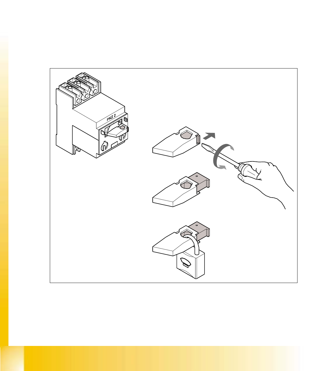
➠ Switch off the motor contactor in the power supply unit and secure the operating lever with a
padlock.
5
Fig. 5.4 - 1 Locking the motor contactor
(1) Turn the operating lever (1) counter-clockwise.
(2) Use the screwdriver to push the locking lug (2) out of the operating lever (1).
(3) Secure the operating lever with a padlock (3).

Student Guide HS-50 Advanced I 06/2002 Edition
5 DLM1 C&P Head
33
– The Tag Out alternative:
If a machine can be locked out, it must be. However, there are situations where energy isolat-
ing devices can not accommodate locks. In these cases, the energy isolating devices must be
tagged to warn employees that the machine is de-energized for servicing. The tag must be se-
curely fastened, it must be placed in a position visible to all and it may only be removed by the
person who attached it. 5
WARNING
To avoid damaging the revolver head, ALWAYS observe the following points when moving
the gantry: 5
– NEVER move the gantry by pushing with your hands against the revolver head.
– NEVER move the gantry by pushing with your hands against or pulling the recessed grip of
the revolver head. The revolver head may lose its settings or be damaged on account of
the high braking force of the Y-gantry drive.
– NEVER push the gantry while the Z-axis is lowered.
– Take hold of the cast iron part of the X-axis - ideally near the X-axis toothed belt deflection
pulley - and then move the gantry.