HS50_advance_level 1_20200522_221201 (1).pdf - 第126页
06/2002 E dition Studen t Guide H S-50 Advance d I 5 DLM1 C&P H ead 34 5.4. 2 Overview fr ont p art of th e head 5. 4.2. 1 Fro nt pa rt, compl ete / DLM 1 The f ront part is centered b y two ho les (B) into whic h th…

Student Guide HS-50 Advanced I 06/2002 Edition
5 DLM1 C&P Head
33
– The Tag Out alternative:
If a machine can be locked out, it must be. However, there are situations where energy isolat-
ing devices can not accommodate locks. In these cases, the energy isolating devices must be
tagged to warn employees that the machine is de-energized for servicing. The tag must be se-
curely fastened, it must be placed in a position visible to all and it may only be removed by the
person who attached it. 5
WARNING
To avoid damaging the revolver head, ALWAYS observe the following points when moving
the gantry: 5
– NEVER move the gantry by pushing with your hands against the revolver head.
– NEVER move the gantry by pushing with your hands against or pulling the recessed grip of
the revolver head. The revolver head may lose its settings or be damaged on account of
the high braking force of the Y-gantry drive.
– NEVER push the gantry while the Z-axis is lowered.
– Take hold of the cast iron part of the X-axis - ideally near the X-axis toothed belt deflection
pulley - and then move the gantry.
06/2002 Edition Student Guide HS-50 Advanced I
5 DLM1 C&P Head
34
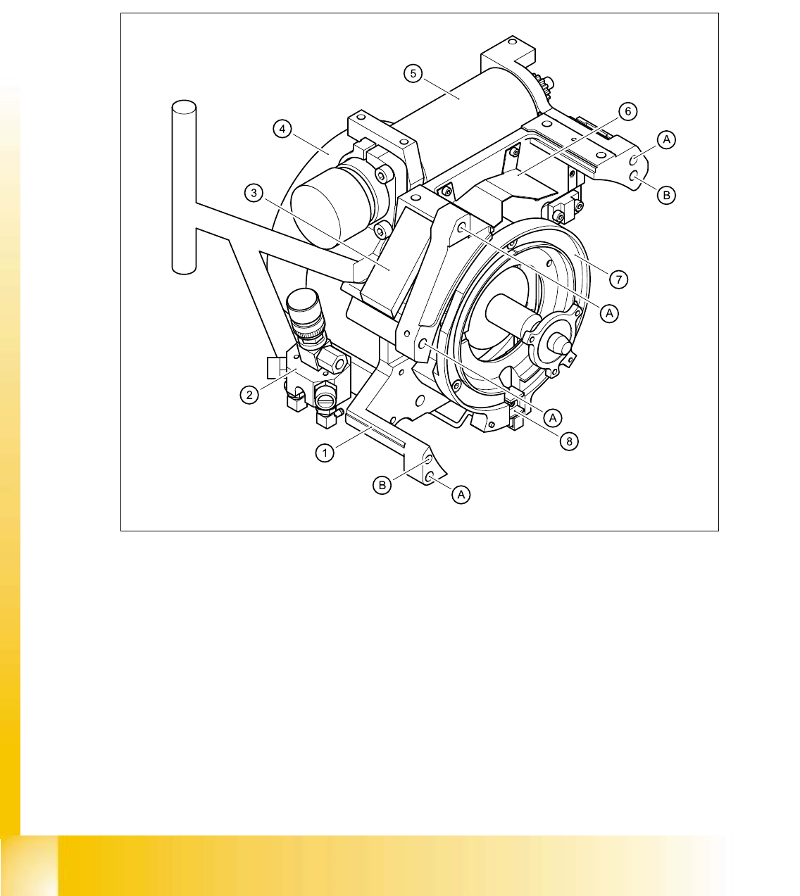
5.4.2 Overview front part of the head
5.4.2.1 Front part, complete / DLM1
The front part is centered by two holes (B) into which the parallel pins of the back part engage.
The front is fixed to the back part with four M4x16 hexagon-socket head screws (item A). 5
5
Fig. 5.4 - 2 Structure of the front part / DLM1
(1) Casing / DLM1
(2) Forced air unit / DLM1
(3) RSF digital rotary encoder / DLM1 (beneath the board with the protective cover)
(4) Star drive, digital / DLM1
(5) Z-axis drive
(6) Protective shroud, front part / DLM1
(7) Raceway for the 12 ball bearings on the segments
(8) Snap jaws raising or lowering the sleeve
Student Guide HS-50 Advanced I 06/2002 Edition
5 DLM1 C&P Head
35
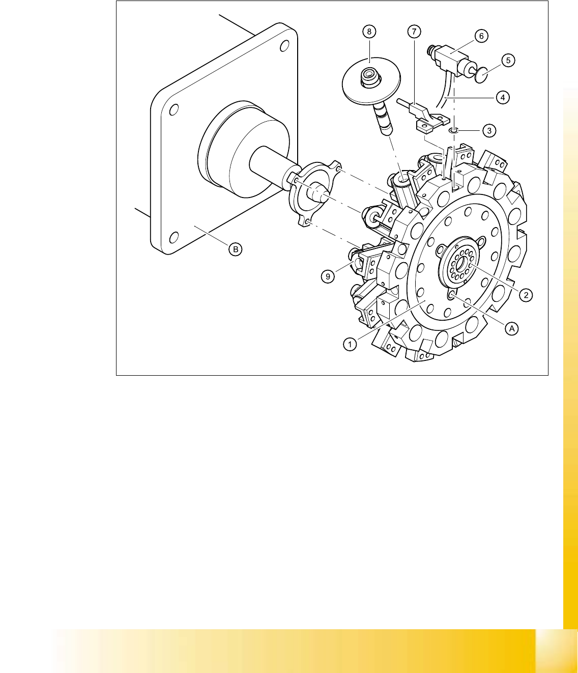
5.4.2.2 Star, fitted / DLM1
The star is fixed to the drive shaft of the star motor (B) with three M3x8 hexagon-socket head
screws (item A). 5
5
Fig. 5.4 - 3 Structure of the star
(1) Star
(2) Distributor plate for distributing the vacuum between the individual segments
(3) 12 O-rings
(4) 12 connecting hoses / DLM1
(5) 12 valve plungers, complete, SP-12
(6) 12 valves, SP-12
(7) 12 forced air inlets
(8) 12 sleeves
(9) 12 segments