HS50_advance_level 1_20200522_221201 (1).pdf - 第128页
06/2002 E dition Studen t Guide H S-50 Advance d I 5 DLM1 C&P H ead 36 5.4. 3 Dismantling / f itting the front p art of th e revo lver head 5.4. 3.1 T ools and equipm ent – Set of DIN 91 1 Allen keys – SITES T progra…
Student Guide HS-50 Advanced I 06/2002 Edition
5 DLM1 C&P Head
35
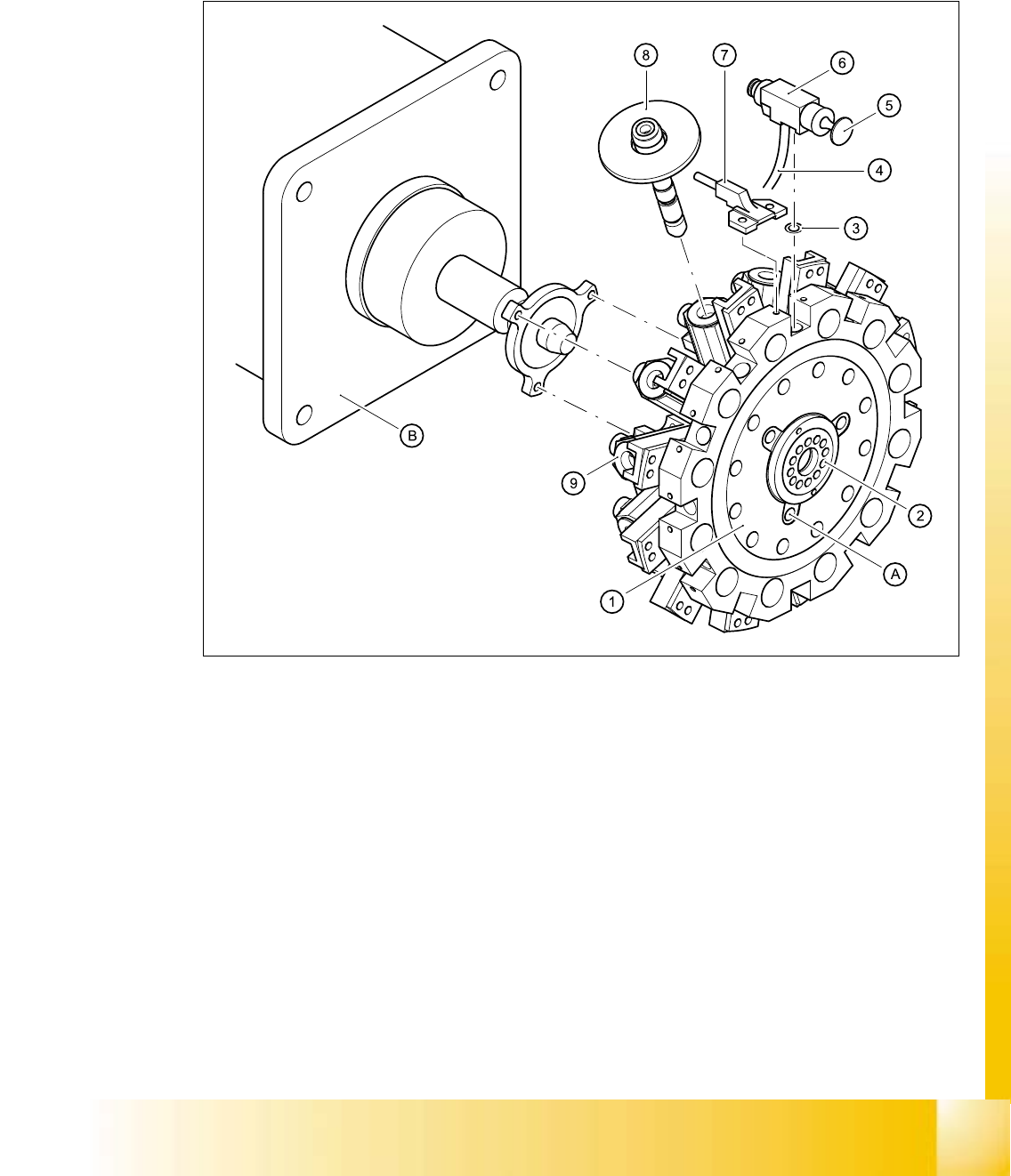
5.4.2.2 Star, fitted / DLM1
The star is fixed to the drive shaft of the star motor (B) with three M3x8 hexagon-socket head
screws (item A). 5
5
Fig. 5.4 - 3 Structure of the star
(1) Star
(2) Distributor plate for distributing the vacuum between the individual segments
(3) 12 O-rings
(4) 12 connecting hoses / DLM1
(5) 12 valve plungers, complete, SP-12
(6) 12 valves, SP-12
(7) 12 forced air inlets
(8) 12 sleeves
(9) 12 segments
06/2002 Edition Student Guide HS-50 Advanced I
5 DLM1 C&P Head
36
5.4.3 Dismantling / fitting the front part of the revolver head
5.4.3.1 Tools and equipment
– Set of DIN 911 Allen keys
– SITEST program
– Adjustment instructions
CAUTION Be careful with the glass scales in the sleeves. They are very fragile. 5
5.4.3.2 Dismantling the front part of the revolver head
➠ Switch the placement system off and secure it to prevent switching on again as described in
section 5.4.1
, page - 32.
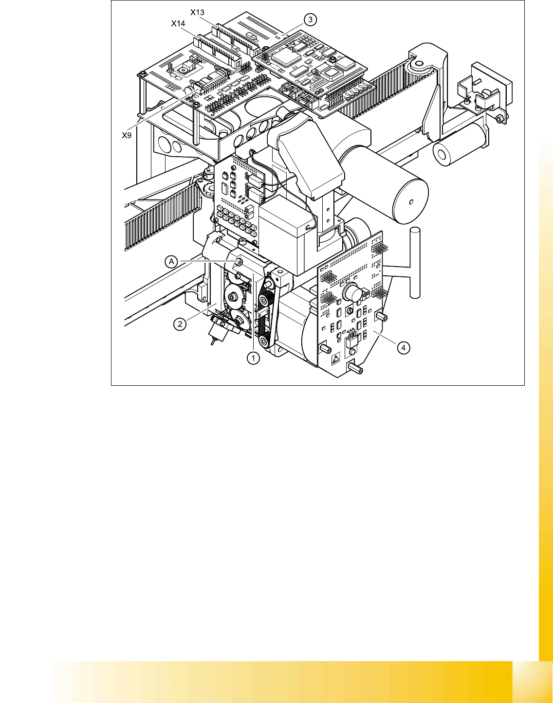
➠ Remove the connecting cable plugs from sockets X9, X13, X14 on the head board (item 3 in
Fig. 5.4 - 4
).
➠ Push the collar of the compressed air coupling (item B in Fig.5.4 - 5) for the air blast unit in the
direction indicated by the arrow. Detach the black compressed air hose and pull it out of the
cable clip (item C in Fig. 5.4 - 5
).
➠ Pull the hose for the placement circuit vacuum check out of the cable clip.
➠ Loosen the four M3x16 hexagon socket head screws (item A in Figs. 5.4 - 4 and 5.4 - 5).
CAUTION When you loosen the last screw, hold the revolver head so that it does
not accidentally drop off the back part. 5
CAUTION When you remove the front part of the revolver head, make sure that
the star is pivoted roughly 15° away from the vertical sleeve position. Otherwise the valve
plunger will remain attached to the valve actuator. 5
➠ Lift the front part of the revolver head away from the parallel pins on the back part and place
on a soft, clean surface.
Student Guide HS-50 Advanced I 06/2002 Edition
5 DLM1 C&P Head
37
. 5
Fig. 5.4 - 4 Dismantling / fitting the front part of the revolver head - part 1
(1) Front part of the revolver head
(2) Back part of the revolver head
(3) Head board
(4) Intermediate distribution board
X9 Plug for the component camera and component illumination system
X13 to plug X2 on the intermediate distribution board (4)
X14 to plug X1 on the intermediate distribution board (4)
(A) Loosen the M4x16 hexagon socket-head screw 5