HS50_advance_level 1_20200522_221201 (1).pdf - 第131页
Studen t Guide HS-50 A dvanced I 06/200 2 Edition 5 DLM1 C&P Head 39 5. 4.3. 3 Fit ti ng t he f ront pa rt o f th e rev olv er head 5 F ig. 5 .4 - 6 T u rn the s tar ap pro xim ate ly 15 °fro m th e v ert ica l sle e…
06/2002 Edition Student Guide HS-50 Advanced I
5 DLM1 C&P Head
38
5
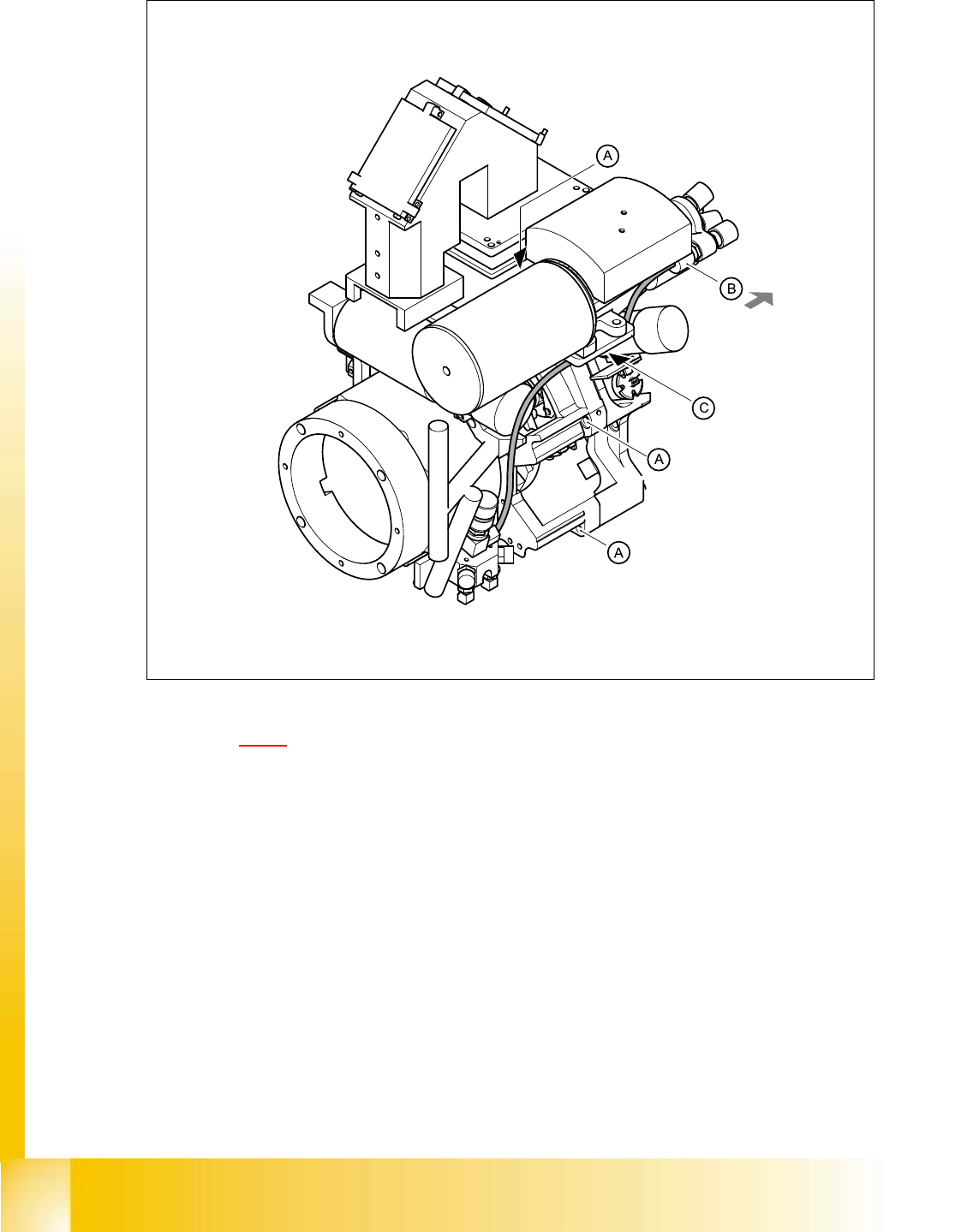
Fig. 5.4 - 5 Dismantling / fitting the front part of the revolver head - part 2
Key to Fig. 5.4 - 5
(A) Hexagon socket-head screws
(B) Push the collar of the compressed air coupling in the direction indicated by the arrow, detach
the black compressed air line and pull it out of the cable clip (C).
Student Guide HS-50 Advanced I 06/2002 Edition
5 DLM1 C&P Head
39
5.4.3.3 Fitting the front part of the revolver head
5
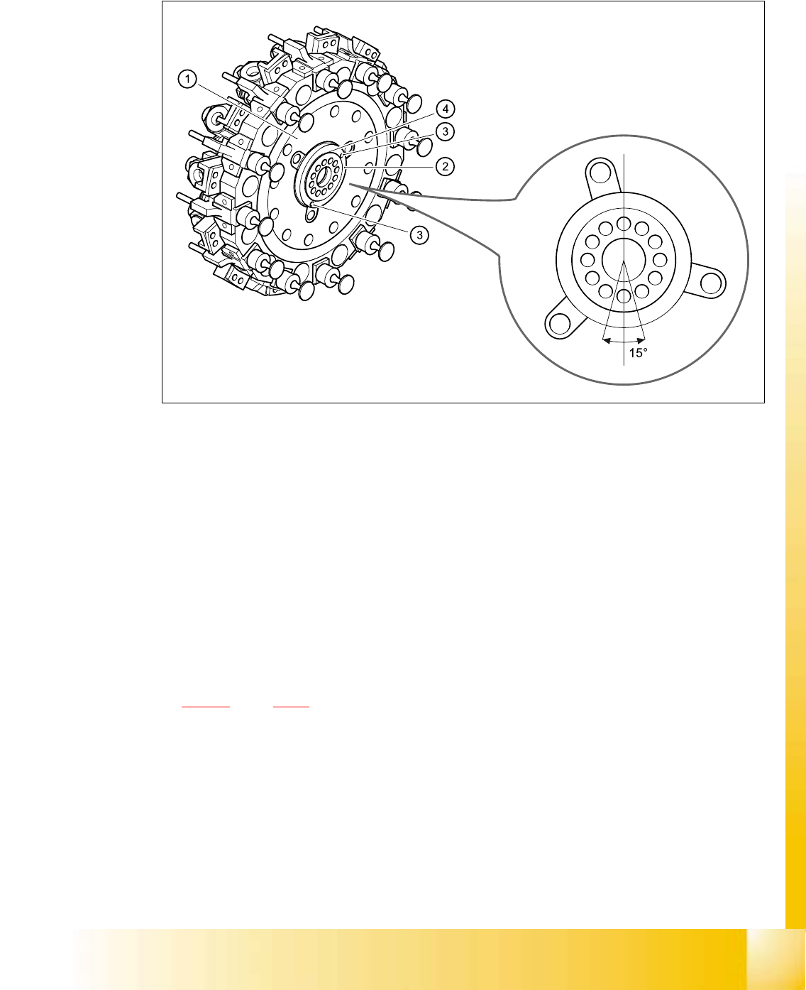
Fig. 5.4 - 6 Turn the star approximately 15°from the vertical sleeve position for installation position of the distributor
plate
(1) Star
(2) Distributor plate
(3) Parallel pins
(4) Raised part of the distributor plate
5
5
➠ Grease the O-rings with Unisilikon.
➠ Push the small O-ring onto the tube.
➠ Place the large O-ring in the hole for the distributor block (item 7 in Fig.
5.4 - 24
, page 5 - 68).
➠ Check that the O-rings are seated correctly.
➠ Insert the distributor block into the back part.
➠ Check that the distributor plate is inserted correctly:
– The circular raised part (4) of the distributor plate (2) the back part of the revolver head.
– The parallel pins (3) on the star engage in the holes in the distributor plate.
➠ Turn the star approximately 15° away from the vertical sleeve position.

06/2002 Edition Student Guide HS-50 Advanced I
5 DLM1 C&P Head
40
➠ Place the front part on the back part so that the parallel pins are aligned with the holes in the
front part.
➠ Carefully the push front part against the back part until it lies flat against the back part.
➠ Attach the M4x16 four hexagon socket-head screws, see item A in Figs. 5.4 - 4 and 5.4 - 5.
➠ Restore the electrical connections (see Fig. 5.4 - 4).
➠ Connect the compressed air hose to the forced air unit (see B in Fig. 5.4 - 5).
PLEASE NOTE: 5
Make sure that the colored part of the ribbon cable for the "Z-axis up" light barrier is pushed
back beneath the illumination board. 5
5.4.3.4 Settings
➠ Start the placement system.
➠ Use the SITEST program to calibrate the component camera.
Cable Head board
00333491-W1 X14
00333491-W2 X13
00341220 X9
Tab. 5.4 - 1 Plug-in connections between front of revolver head and head board