HS50_advance_level 1_20200522_221201 (1).pdf - 第133页
Studen t Guide HS-50 A dvanced I 06/200 2 Edition 5 DLM1 C&P Head 41 5.4. 4 Removal of c o mpo n ent ca mera 5.4. 4.1 T ools and e quipm ent – Set of DIN 91 1 Allen keys – SITES T program 5. 4.4. 2 Pa rt s 24x2 4 com…
06/2002 Edition Student Guide HS-50 Advanced I
5 DLM1 C&P Head
40
➠ Place the front part on the back part so that the parallel pins are aligned with the holes in the
front part.
➠ Carefully the push front part against the back part until it lies flat against the back part.
➠ Attach the M4x16 four hexagon socket-head screws, see item A in Figs. 5.4 - 4 and 5.4 - 5.
➠ Restore the electrical connections (see Fig. 5.4 - 4).
➠ Connect the compressed air hose to the forced air unit (see B in Fig. 5.4 - 5).
PLEASE NOTE: 5
Make sure that the colored part of the ribbon cable for the "Z-axis up" light barrier is pushed
back beneath the illumination board. 5
5.4.3.4 Settings
➠ Start the placement system.
➠ Use the SITEST program to calibrate the component camera.
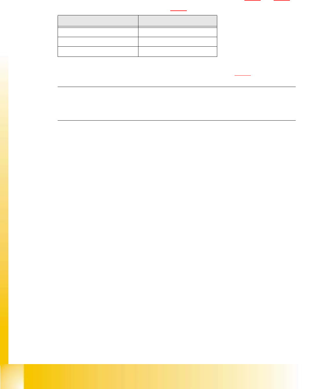
Cable Head board
00333491-W1 X14
00333491-W2 X13
00341220 X9
Tab. 5.4 - 1 Plug-in connections between front of revolver head and head board

Student Guide HS-50 Advanced I 06/2002 Edition
5 DLM1 C&P Head
41
5.4.4 Removal of component camera
5.4.4.1 Tools and equipment
– Set of DIN 911 Allen keys
– SITEST program
5.4.4.2 Parts
24x24 component camera, item no. 00320549-04 5
PLEASE NOTE:
The component camera is replaced as a complete unit consisting of the lens system, camera, am-
plifier, illumination planes and "Illumination controller" board. 5
5.4.4.3 Dismantling the component camera
➠ Dismantle the front part of the revolver head as described in section 5.4.3, page - 36 onward.
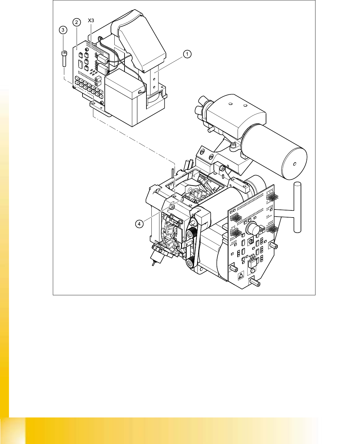
➠ Remove the ribbon cable plug from socket X3 on the "component illumination control" board
(item 5 in Fig. 5.4 - 7
).
➠ Loosen the four M4x10 hexagon socket-head screws for fixing the component camera.
➠ Carefully detach the component camera.
5.4.4.4 Fitting the component camera
➠ Make sure that all contact surfaces are clean.
➠ Place the holes in the camera on the parallel pins (see item 7 in Fig. 5.4 - 7).
06/2002 Edition Student Guide HS-50 Advanced I
5 DLM1 C&P Head
42
5
Fig. 5.4 - 7 Replacing the component camera
(1) 24x24 component camera
(2) "Component illumination controller" board
(3) 4 x M4x10 hexagon-socket head screws
(4) 2 parallel pins
X3 Socket 5
5