HS50_advance_level 1_20200522_221201 (1).pdf - 第134页
06/2002 E dition Studen t Guide H S-50 Advance d I 5 DLM1 C&P H ead 42 5 F ig. 5. 4 - 7 Re pl acin g the c o mpon en t c ame ra (1) 24x24 comp onent camer a (2) "Component illumination c ontroller" board (3…

Student Guide HS-50 Advanced I 06/2002 Edition
5 DLM1 C&P Head
41
5.4.4 Removal of component camera
5.4.4.1 Tools and equipment
– Set of DIN 911 Allen keys
– SITEST program
5.4.4.2 Parts
24x24 component camera, item no. 00320549-04 5
PLEASE NOTE:
The component camera is replaced as a complete unit consisting of the lens system, camera, am-
plifier, illumination planes and "Illumination controller" board. 5
5.4.4.3 Dismantling the component camera
➠ Dismantle the front part of the revolver head as described in section 5.4.3, page - 36 onward.
➠ Remove the ribbon cable plug from socket X3 on the "component illumination control" board
(item 5 in Fig. 5.4 - 7
).
➠ Loosen the four M4x10 hexagon socket-head screws for fixing the component camera.
➠ Carefully detach the component camera.
5.4.4.4 Fitting the component camera
➠ Make sure that all contact surfaces are clean.
➠ Place the holes in the camera on the parallel pins (see item 7 in Fig. 5.4 - 7).
06/2002 Edition Student Guide HS-50 Advanced I
5 DLM1 C&P Head
42
5
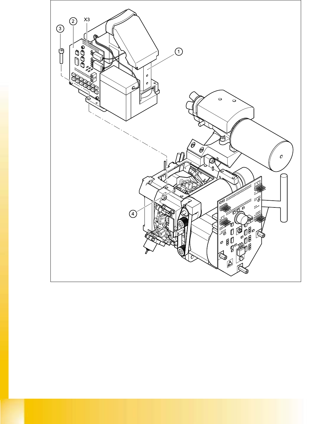
Fig. 5.4 - 7 Replacing the component camera
(1) 24x24 component camera
(2) "Component illumination controller" board
(3) 4 x M4x10 hexagon-socket head screws
(4) 2 parallel pins
X3 Socket 5
5

Student Guide HS-50 Advanced I 06/2002 Edition
5 DLM1 C&P Head
43
➠ Carefully push the camera against the revolver head until the camera plinth is lying flat on the
contact surfaces on the front part of the revolver head.
➠ Use the four M4x10 hexagon socket-head screws to fix the camera in place (see item 6 in Fig.
5.4 - 7
).
➠ Connect the ribbon cable to socket X3 on the "component illumination" board (item X3 in
Fig. 5.4 - 7
).
➠ Fit the front part of the revolver head as described in section 5.4.3.3, page 5 - 39.
➠ Fix the head cover in place.
5.4.4.5 Settings
➠ Start the placement system.
➠ Use the SITEST program to calibrate the revolver head.
5.4.5 Removal of star
5.4.5.1 Tools and equipment
– Set of DIN 911 Allen keys
– Gauge for the star (revolver head / DLM1), article number 00326164-01
– Power pack for the revolver head / DLM1, article number 00353277-01
– Tray for transporting the revolver head
– Laboratory gloves
5.4.5.2 Parts
Star, mounted / DLM1, article number 00341181-01 5
5.4.5.3 Dismantling the star
➠ Dismantle the front part of the revolver head as described in section 5.4.3, page - 36 onwards.
➠ Place the front part of the revolver head on the tray.
PLEASE NOTE:
Wear laboratory gloves when you remove the sleeves from the star. 5
➠ Remove all the sleeves (item 1 in Fig. 5.4 - 8) and place them in the sleeve box or on a soft,
clean surface.
➠ Loosen the three M3x8 hexagon socket head screws (item 5 in Fig. 5.4 - 8).
➠ Raise the star slightly.
➠ Use a rotary movement to lift the star up and off.